Camera socket connector

a technology of camera socket and connector, which is applied in the direction of electrical equipment, connection, coupling device connection, etc., can solve the problems of increasing costs, increasing manufacturing difficulty, increasing complexity of insulation body structure, and reducing structural strength, so as to reduce the number of components, simplify the product structure, and reduce the difficulty and cost of manufacturing

Inactive Publication Date: 2012-02-02
MOLEX INC
View PDF4 Cites 10 Cited by
  • Summary
  • Abstract
  • Description
  • Claims
  • Application Information

AI Technical Summary

Benefits of technology

[0009]The fixed parts of the conductive terminals are all securely buried into the side walls of the insulation body by means of insertion molding. In contrast to the prior art, the electrical connector can reduce the number of components and thereby simplify the product structure, because the insulation body equipped with conductive terminals is assembled onto the shielding housing, and because the fixed parts of the conductive terminals are injected using an insertion molding process and buried on the side walls of the insulation body; also, the lack of a need to provide receiving grooves for the conductive terminals on the insulation body can reduce the difficulty and costs of manufacturing the mold.

Problems solved by technology

However, such an insertion and combination of the signal terminals necessitates that a plurality of receiving grooves be provided on the side walls of the insulation body to correspondingly receive the fixed parts of the signal terminals, thereby making the structure of the insulation body more complicated and making the manufacture of the corresponding injection mold more difficult and increasing costs.
Moreover, providing a plurality of receiving grooves on the insulation body may reduce the structural strength thereof, such that the same may be easily damaged.
Although there is no need to provide a plurality of conductive terminal receiving grooves on the insulation bodies of an electrical connector structured in this way, the electrical connector structured in this way comprises the five components of a casing, a pair of insulation bodies and a pair of shielding casings, which components are too numerous such that the machining and assembly steps are cumbersome and complex.

Method used


Image

  • Camera socket connector
  • Camera socket connector
  • Camera socket connector

Examples


Embodiment Construction

[0024]The following incorporates the drawings to show an example of a connector adapter suitable for connecting a group of camera modules on a mobile phone, so as to provide a more detailed description. The technical problems which the disclosure can help address are the above insufficiencies found in the prior art, and to provide an electrical connector wherein the product structure can be simplified and at the same time reducing the difficulty and costs of production.

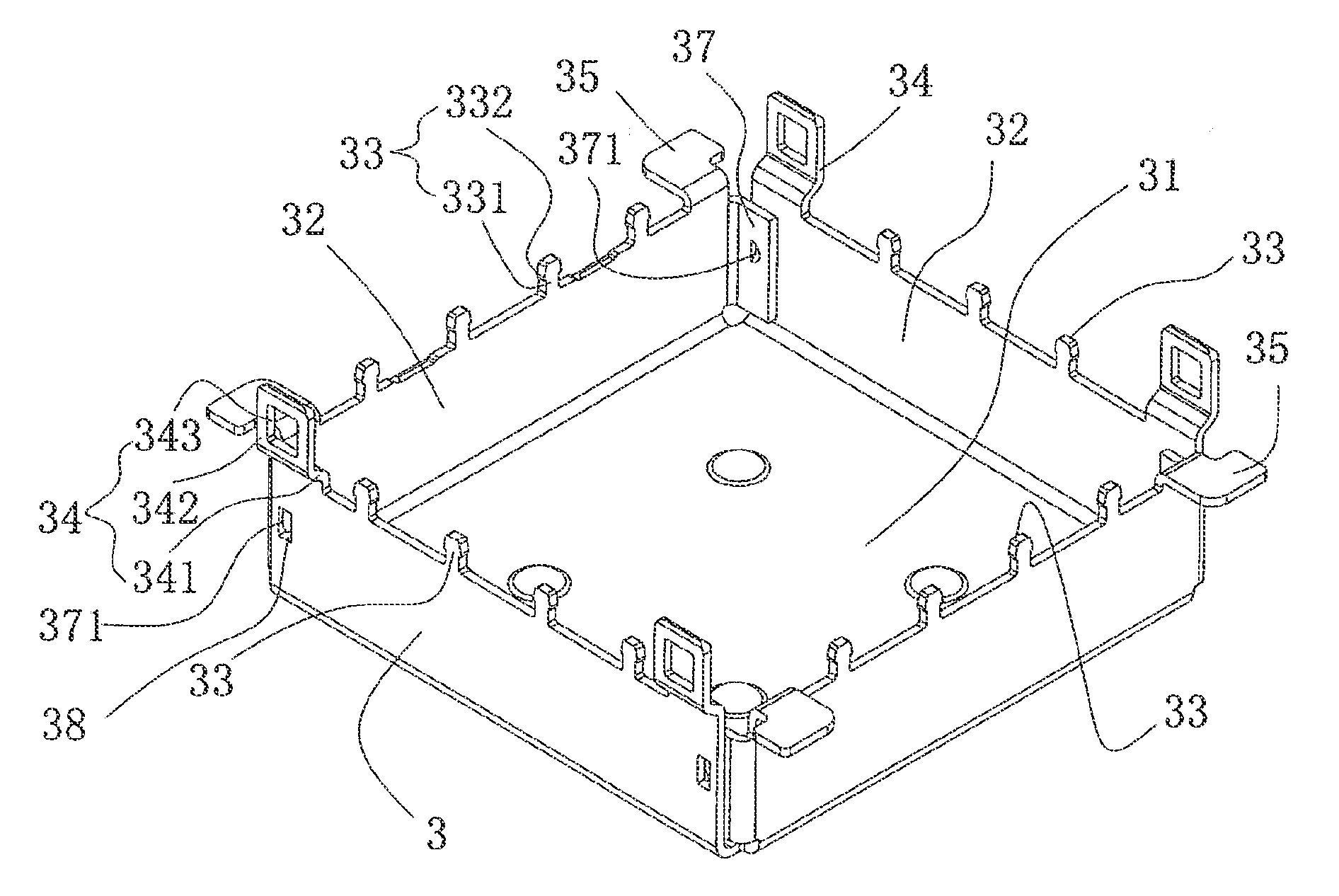
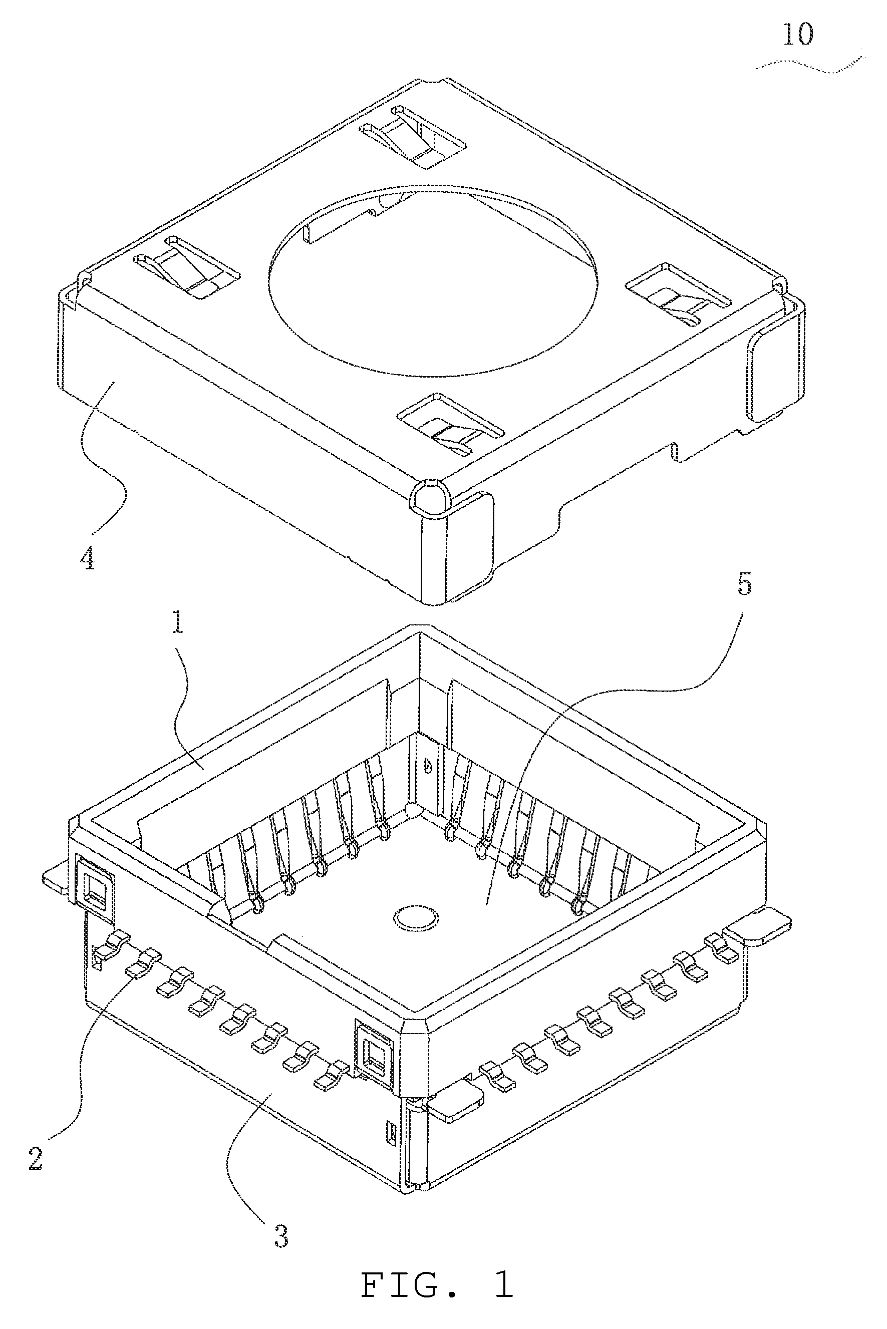
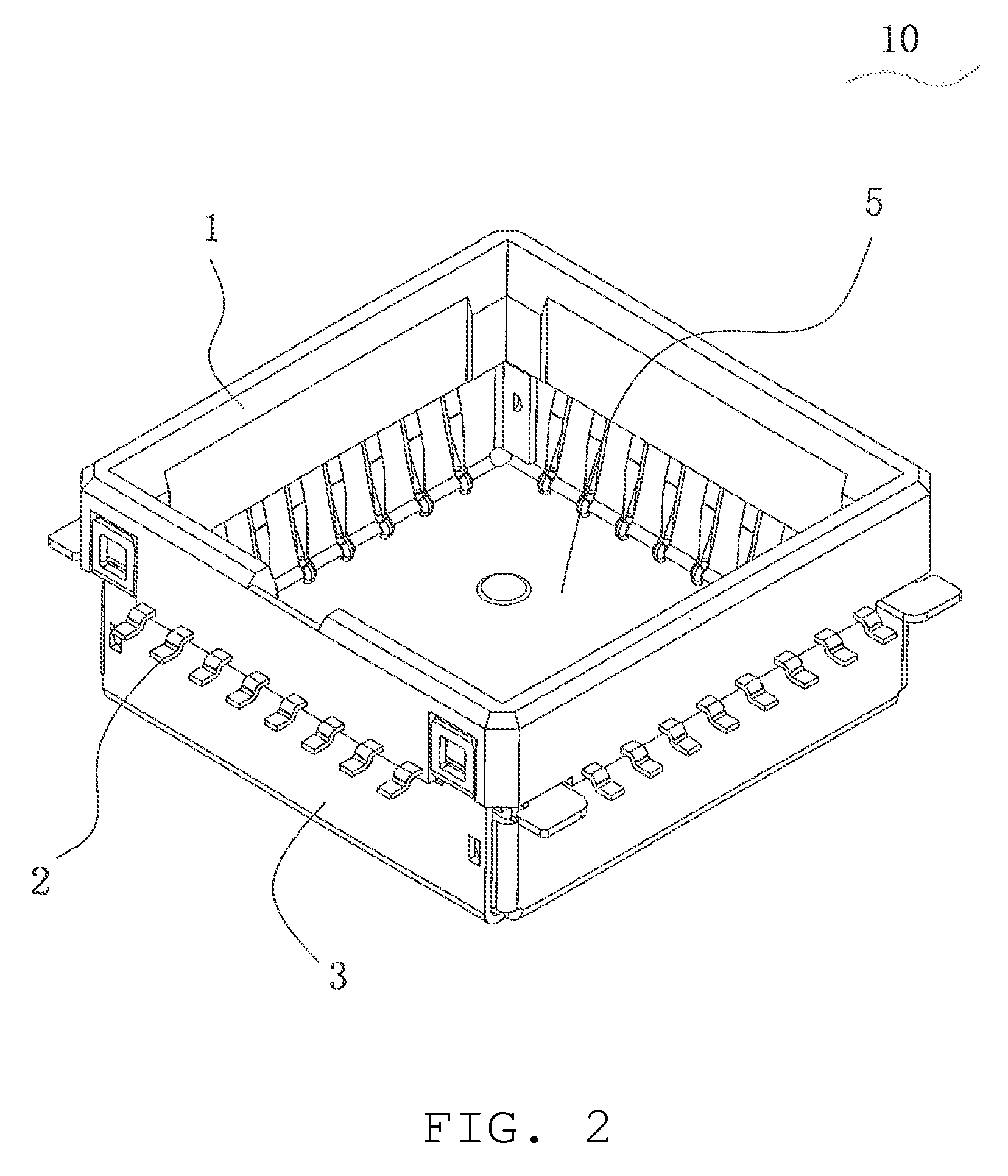
[0025]FIGS. 1 to 6 show the components of the main body of an embodiment of electrical connector 10, comprising insulation body 1, a plurality of conductive terminals 2 installed on insulation body 1, and shielding housing 3 installed beneath insulation body 1. In addition to the above components of the main body, an embodiment of electrical connector 10 may further comprise cover 4, which can cover the upper exterior of insulation body 1.

[0026]FIGS. 3 to 6 are incorporated below to further describe the structure of t...


PUM


Abstract

An electrical connector suitable for correspondingly housing an electronic module, the electrical connector comprising an insulation body, a plurality of conductive terminals installed on the insulation body, and a shielding housing, wherein the insulation body is a square frame enclosed by four side walls, and the shielding housing is installed beneath the insulation body, comprising a bottom wall and four side walls extending upwards from the bottom wall, wherein the tops of the four side walls of the shielding housing are correspondingly joined to the bottom of the four side walls of the insulation body so as to jointly form an electronic module receiving space which opens upward, and wherein each of the conductive terminals comprises a docking part extending into the receiving space, a welded part extending out of the insulation body, and a fixed part fixed onto a side wall of the insulation body.

Description

RELATED APPLICATIONS[0001]This application claims priority to Chinese Application No. 201010218751.2, filed Jun. 30, 2010, which is incorporated herein by reference in its entirety.FIELD OF THE INVENTION[0002]The present invention relates to an electrical connector, and in particular relates to an electrical connector for housing a camera module.DESCRIPTION OF THE RELATED ART[0003]With the development of electronic technology, there is a demand to install an increasingly greater number of electrical connectors in order to attach various kinds of electronic modules (such as camera modules having photographic functions) to electronic products such as mobile telephones, personal digital assistants (PDAs), and notebook computers to meet the usage demands of consumers.[0004]Current electrical connectors used to house camera modules, such as the electrical connector disclosed by Chinese patent CN2775870Y, are installed onto a circuit board, the electrical connector comprising an insulatio...

Claims


Application Information

Patent Timeline
Patent Type & Authority Applications(United States)
IPC IPC(8): H01R9/03
CPCH01R13/6594
Inventor CHENG, XING-JUN
Owner MOLEX INC
Why Eureka
Try Eureka