Composite Rod for Spinal Implant Systems With Higher Modulus Core and Lower Modulus Polymeric Sleeve

Inactive Publication Date: 2012-02-02
WARSAW ORTHOPEDIC INC
View PDF59 Cites 16 Cited by
  • Summary
  • Abstract
  • Description
  • Claims
  • Application Information

AI Technical Summary

Benefits of technology

[0006]An embodiment of the invention may include a spinal rod having a core component and a tube. The core component has a radius. The tube has a first state with a first state tube inner radius and a first state tube outer radius. The first state tube inner radius is greater than the core component radius. The tube has a second state with a second s

Problems solved by technology

Damage to one or more components of the spinal column, such as an intervertebral disc, may result from disease or trauma and cause instability of the spinal column and damage multiple biomechanical functions of the spinal column.
There are some disadvantages associated with the use of rigid spinal fixation devices, including decreased mobility, stress shielding (i.e. too little stress on some bones, leading to a decrease in bone density), and stress localization (i.e. too much stress on some bones, leading to fracture and other damage).

Method used


Image

  • Composite Rod for Spinal Implant Systems With Higher Modulus Core and Lower Modulus Polymeric Sleeve
  • Composite Rod for Spinal Implant Systems With Higher Modulus Core and Lower Modulus Polymeric Sleeve
  • Composite Rod for Spinal Implant Systems With Higher Modulus Core and Lower Modulus Polymeric Sleeve

Examples


Embodiment Construction

[0018]For the purposes of promoting an understanding of the principles of the invention, reference will now be made to the embodiments, or examples, illustrated in the drawings and specific language will be used to describe the same. It will nevertheless be understood that no limitation of the scope of the invention is thereby intended. Any alterations and further modifications in the described embodiments, and any further applications of the principles of the invention as described herein are contemplated as would normally occur to one skilled in the art to which the invention relates.

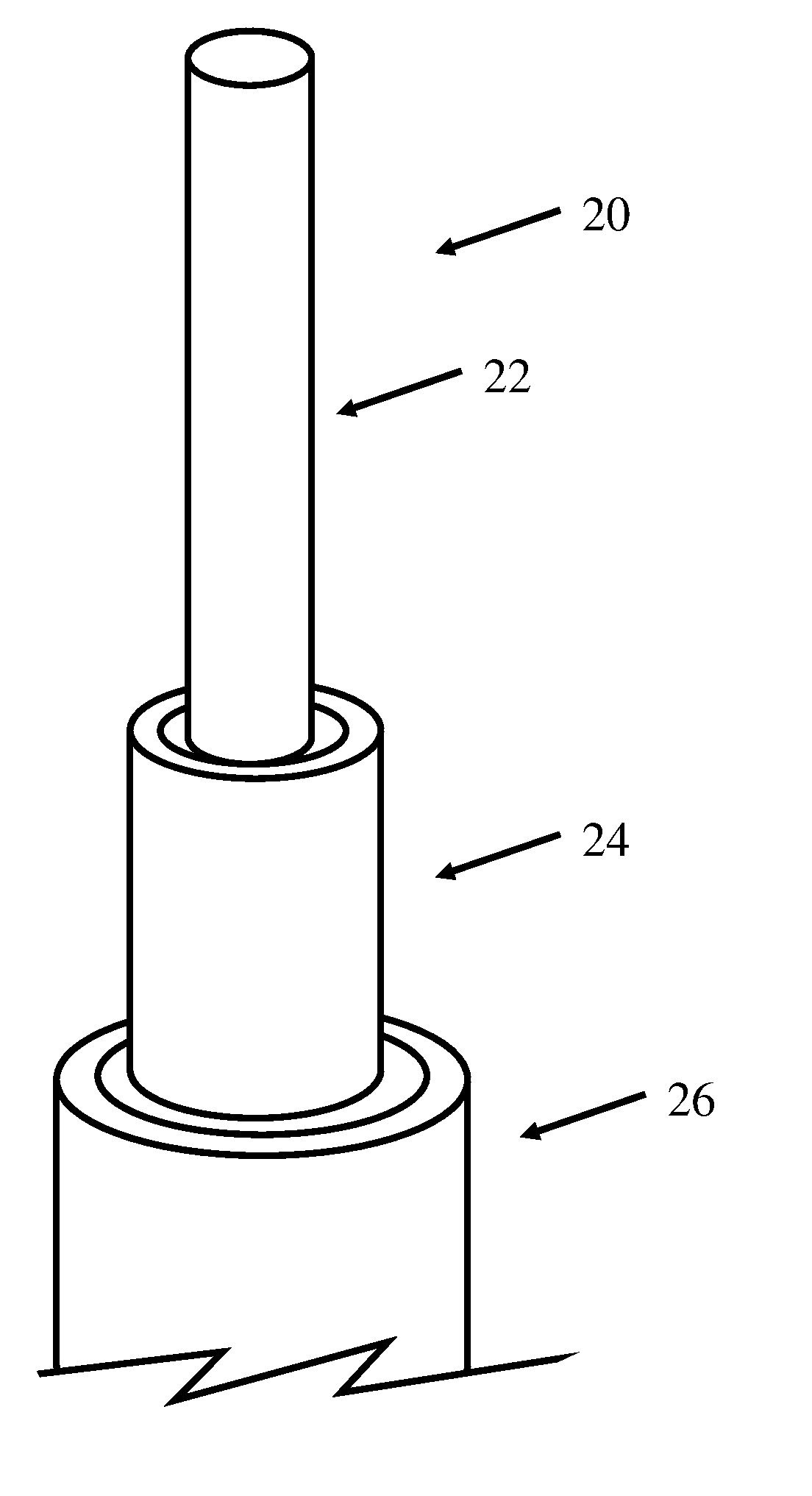
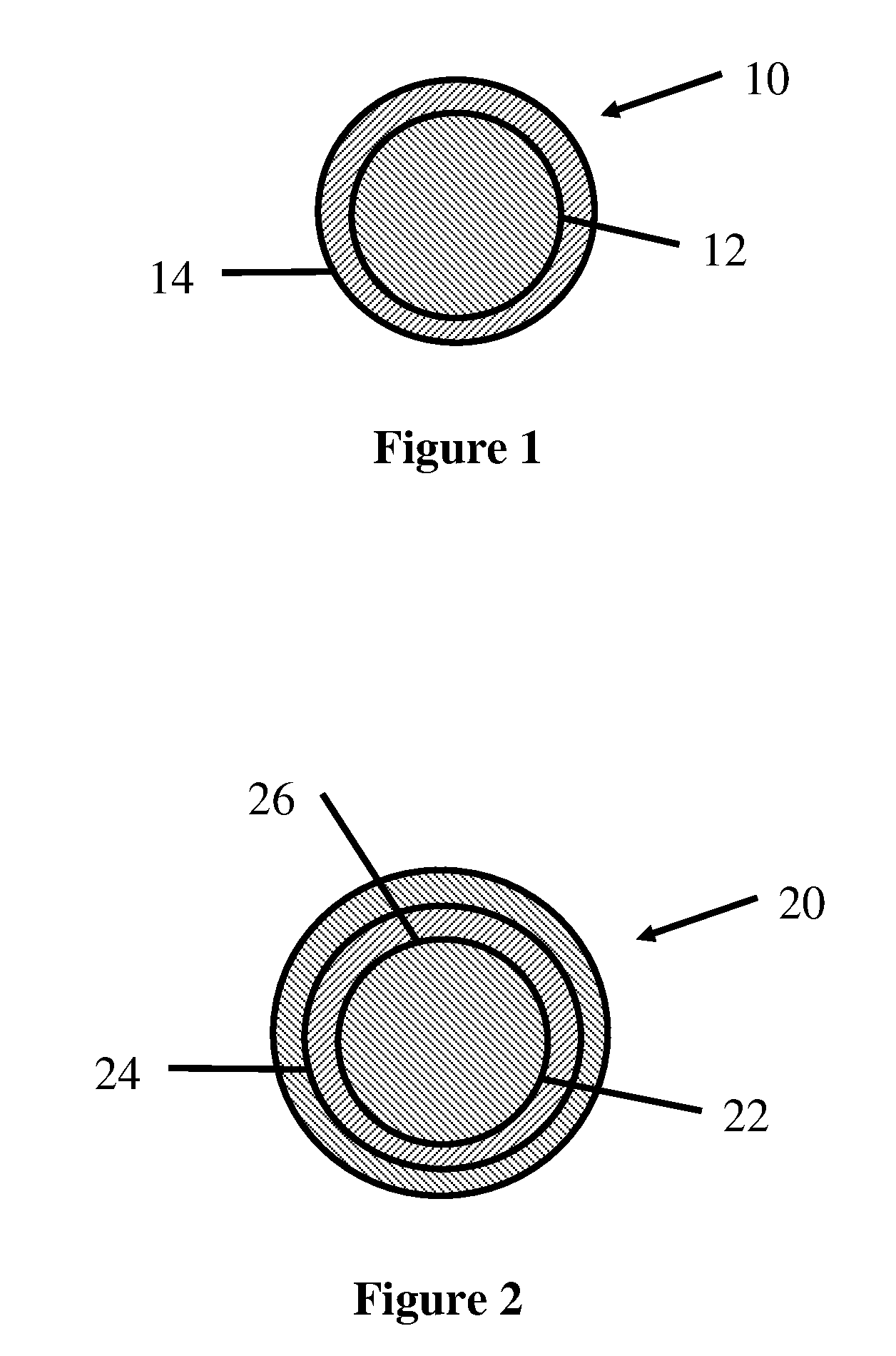
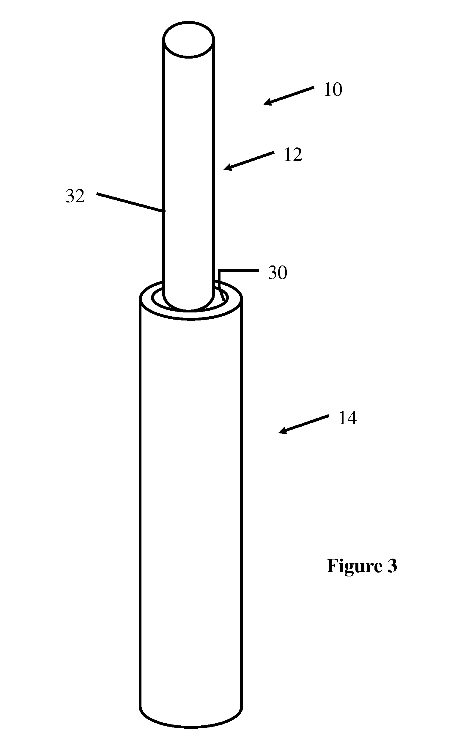
[0019]It is a feature of an embodiment of the present invention to provide composite rods for use in spinal fixation systems. The composite components may comprise a first core material which may be a metal, metal alloy, a polymer, or a polymeric composite; and a second material formed in a sleeve and selected from the group consisting of resorbable and non-resorbable polymeric materials. In a preferr...


PUM

PropertyMeasurementUnit
Fractionaaaaaaaaaa
Thicknessaaaaaaaaaa
Thicknessaaaaaaaaaa

Abstract

A spinal rod includes a metal component and a tube. The core component has a radius. The tube has a first state with a first state tube inner radius and a first state tube outer radius. The first state tube inner radius is greater than the core component radius. The tube has a second state with a second state tube inner radius and a second state tube outer radius. The second state tube inner radius is generally equal to the core component radius. The tube is deformable from the first state to the second state.

Description

FIELD OF INVENTION[0001]Embodiments of the invention relate to spinal fixation systems having at least one composite component. More particularly, the embodiments relate to rods for use in spinal fixation systems that are composites of polyetheretherketone (PEEK) and metals or metal alloys.BACKGROUND[0002]The spinal column is a biomechanical structure composed primarily of support structures including vertebrae and intervertebral discs and soft tissue structures for motive and stabilizing forces including muscles and ligaments. The biomechanical functions of the spinal column include support, spinal cord protection, and motion control between the head, trunk, arms, pelvis, and legs. These biomechanical functions may require oppositely designed structures. For example, the support function may be best addressed with rigid load bearing structures while motion control may be best suited for structures that are easily movable relative to each other. The trade-offs between these biomecha...

Claims


Application Information

Patent Timeline
IPC IPC(8): A61B17/70B23P11/02
CPCA61B17/7029Y10T29/49865A61B2017/00004A61B17/7031
Inventor TRIEU, HAI H.PREVOST, JULIEN J.
Owner WARSAW ORTHOPEDIC INC
Why Eureka
Try Eureka