Bone Cage with Components for Controlled Expansion

a bone cage and component technology, applied in the field of implants, can solve the problems of severe neurological injury or paralysis, pain, infection or weakness in the area where the graft is taken, and patient discomfort is considerable, and achieves the effect of reducing the risk of infection or weakness, and reducing the risk of infection

Inactive Publication Date: 2012-02-02
RAGAB ASHRAF A +1
View PDF11 Cites 195 Cited by
  • Summary
  • Abstract
  • Description
  • Claims
  • Application Information

AI Technical Summary

Benefits of technology

[0076]The present invention is an expandable and adjustable bone cage designed to be used in conjunction with a pedicle screw or plating fusion system. The expandable and adjustable bone cage provides structure for the placement of bone graft material between two adjacent vertebral bodi

Problems solved by technology

When bone is taken from another part of the patient's own body (i.e., autograft), there is a risk of pain, infection, or weakness in the area where the graft is taken.
A risk associated with the use of bone growth material is that the nerves may be exposed to the material causing bone formations around or adjacent to the nerves, which can cause severe neurological injury or paralysis.
The abdominal muscles must be displaced resulting in considerable patient discomfort and increased recovery time.
The use of bone formation material poses considerable risk since the lumbar nerves are exposed during the procedure.
Any displacement of the bone formation material can cause substantial nerve damage.
However, synthetic bone growth material is not currently approved by the FDA for use in lateral spinal fusion procedures.
A problem known in the art is that when a disc is removed and pedicle screws are inserted, there is a loss of support due to the displacement of the disc material that is normally in contact with the endplates.
In older patients, bone is weaker and the pressure of the pedicle screws can cause osteoporotic complications.
However, devices known in the art are associated with problems due to incomplete or uncontrolled contact between the endplates of the vertebral bodies and the upper and lower surfaces of the cage.
However, these devices cannot be adjusted for a particular patient nor can they be expanded to provide physiologic lordosis (i.e., normal curvature of the lumbar spine where the disc space is wider anteriorly).
The Continental™, Colonial™ and Sustain® O, however, are not desirable because they are not ideally contoured to the shape of the vertebral endplates resulting in a minimal area of contact between the cage and the vertebral endplates.
In addition, each bone cage has a fixed height, which cannot be adjusted after insertion.
None of these bone cages are capable of being adj

Method used


Image

  • Bone Cage with Components for Controlled Expansion
  • Bone Cage with Components for Controlled Expansion
  • Bone Cage with Components for Controlled Expansion

Examples


Embodiment Construction

[0078]For the purpose of promoting an understanding of the present invention, references are made in the text to exemplary embodiments of an expandable and adjustable bone cage, only some of which are described herein. It should be understood that no limitations on the scope of the invention are intended by describing these exemplary embodiments. One of ordinary skill in the art will readily appreciate that alternate but functionally equivalent materials, dimensions and designs may be used. The inclusion of additional elements may be deemed readily apparent and obvious to one of ordinary skill in the art. Specific elements disclosed herein are not to be interpreted as limiting, but rather as a basis for the claims and as a representative basis for teaching one of ordinary skill in the art to employ the present invention.

[0079]It should be understood that the drawings are not necessarily to scale; instead, emphasis has been placed upon illustrating the principles of the invention. In...


PUM


Abstract

The present invention is an expandable and adjustable bone cage designed to be used in conjunction with a pedicle screw or plating fusion system. The expandable and adjustable bone cage provides structure for the placement of bone graft material between two adjacent vertebral bodies in order to stabilize or fuse the spine in a predetermined position. The expandable and adjustable bone cage is contoured for easy insertion between vertebral bodies and may be expanded after insertion to maintain, establish or increase lordosis, as well as help secure the bone cage.

Description

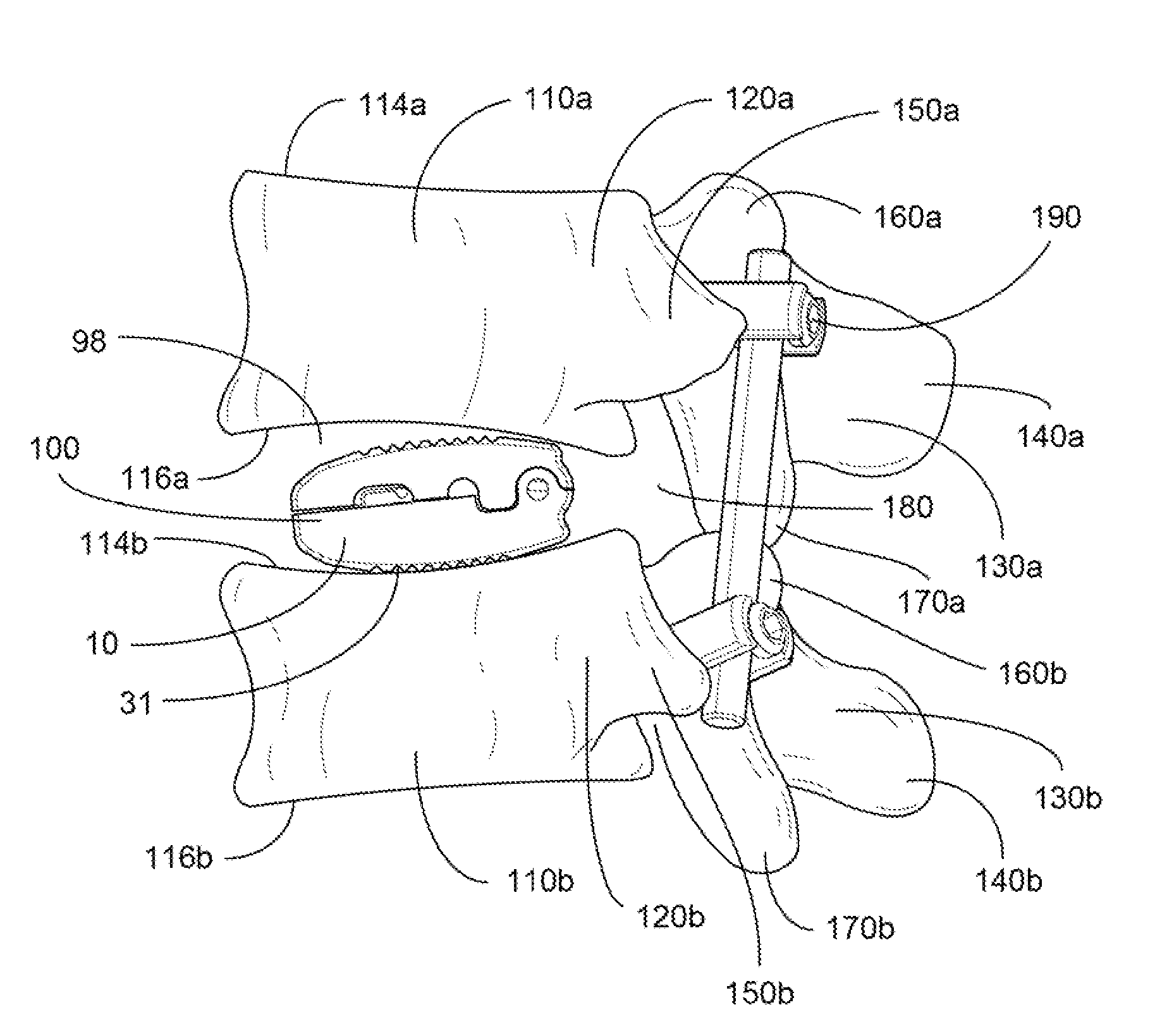
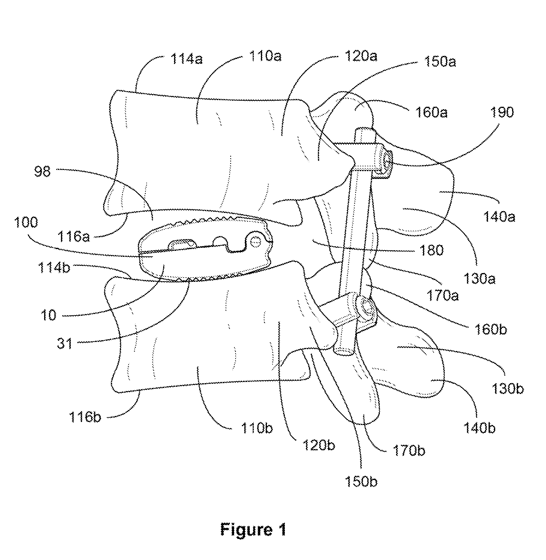
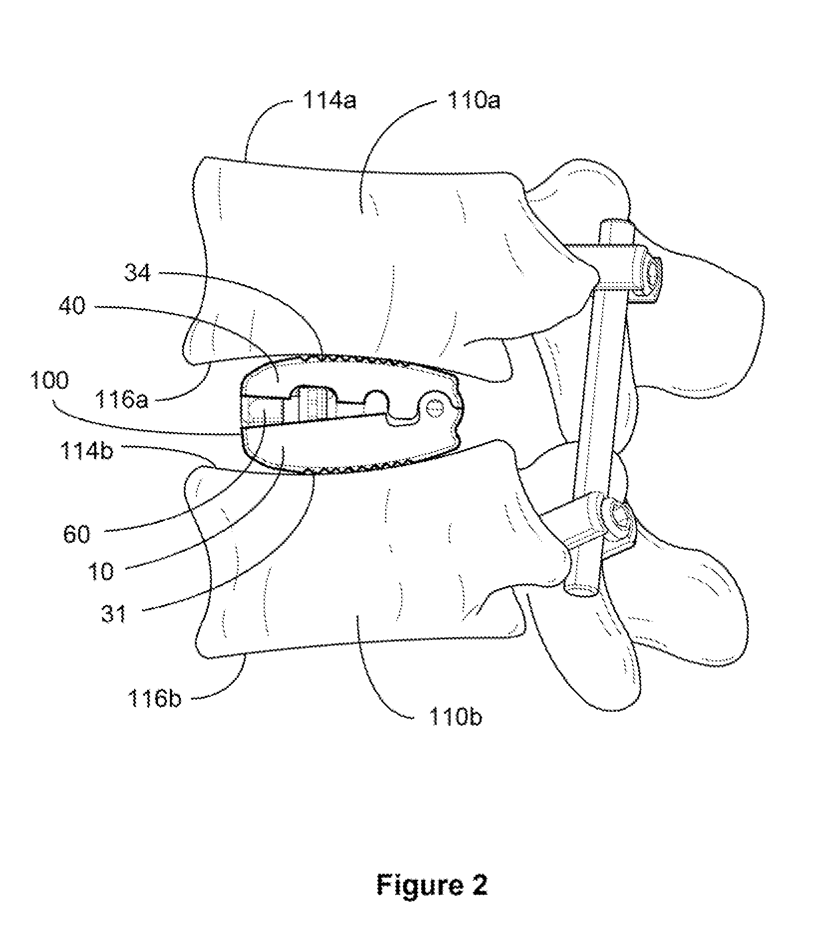
FIELD OF INVENTION[0001]The present invention relates to the field of implants and more particularly to an expandable and adjustable bone cage with a rotatable cam lift for spinal fusions.BRIEF DESCRIPTION OF THE DRAWINGS[0002]FIG. 1 illustrates a left side view of an exemplary embodiment of an expandable and adjustable bone cage implanted and in a closed / first position.[0003]FIG. 2 illustrates a left side view of an exemplary embodiment of an expandable and adjustable bone cage implanted and in an expanded position.[0004]FIG. 3 illustrates a perspective view of the proximal end of an exemplary embodiment of an expandable and adjustable bone cage in a closed / first position.[0005]FIG. 4 illustrates a perspective view of the distal end of an exemplary embodiment of an expandable and adjustable bone cage in a closed / first position.[0006]FIG. 5a illustrates a perspective view of an exemplary embodiment of a cam lift for an expandable and adjustable bone cage.[0007]FIG. 5b illustrates a ...

Claims


Application Information

Patent Timeline
IPC IPC(8): A61F2/44
CPCA61F2/30723A61F2310/00179A61F2/447A61F2002/2817A61F2002/2835A61F2002/30471A61F2002/30482A61F2002/30484A61F2002/30505A61F2002/30517A61F2002/30522A61F2002/30538A61F2002/30556A61F2002/30571A61F2002/30579A61F2002/30604A61F2002/30612A61F2002/30736A61F2002/30904A61F2002/4475A61F2310/00023A61F2/4425A61F2002/30593
Inventor RAGAB, ASHRAF A.RINNER, JAMES A.
Owner RAGAB ASHRAF A
Why Eureka
Try Eureka