
Energy-Absorbing Device Particularly For A Shock Absorber For A Track-Guided Vehicle

a track-guided vehicle and energy-absorbing device technology, which is applied in the direction of shock absorbers, bumpers, vehicular safety arrangments, etc., can solve the problems of insufficient drawgear to absorb all of the resulting energy on its own, damage or even destruction, and achieve the effect of preventing the relative twisting of the counter elemen

Inactive Publication Date: 2012-02-09
VOITH PATENT GMBH
View PDF1 Cites 27 Cited by
  • Summary
  • Abstract
  • Description
  • Claims
  • Application Information

AI Technical Summary

Benefits of technology

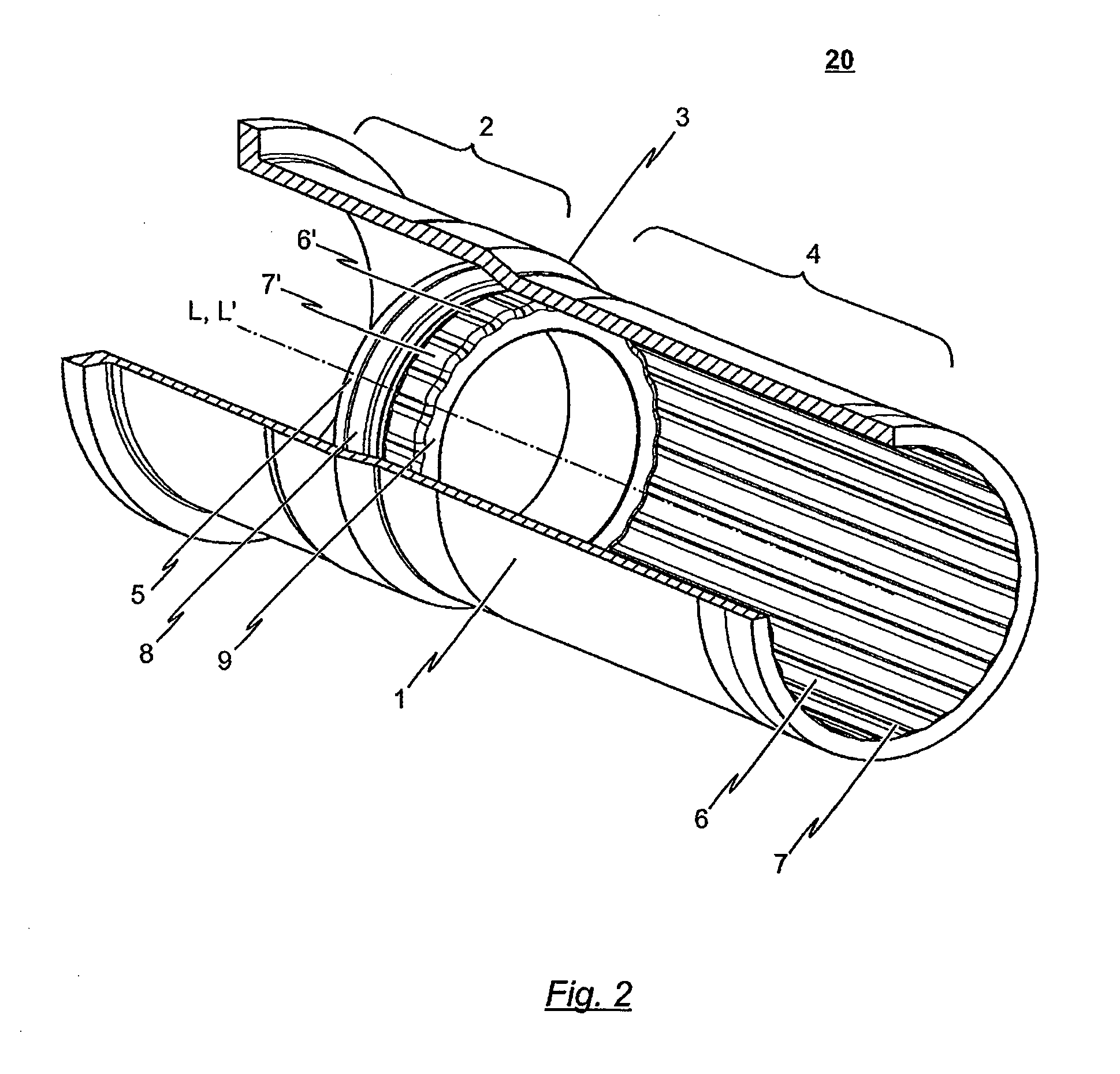
[0009]The present invention is thus directed to an energy absorbing device containing a deformation tube and counter element which is capable of absorbing energy predictably, regardless of whether the energy conveyed to the energy absorbing device is parallel or oblique to the longitudinal axis of the deformation tube. These and other objects are achieved by a device in which the counter element is connected to the deformation tube by a form-fit connection circumferential to the deformation tube, which effectively prevents twisting of the counter element relative to the deformation tube.

Problems solved by technology

However, when the operating load of the drawgear is exceeded, for instance upon the vehicle colliding with an obstacle, the drawgear and any articulated or coupling connection provided as an interface between the individual car bodies may possibly be destroyed or damaged.
At higher collision energies, the drawgear is insufficient to absorb all of the resulting energy on its own.
There is thereby the risk that the vehicle underframe or the entire car body will be used to absorb further energy, which subjects these components to extreme loads which may possibly damage or even destroy them.
In such cases, rail vehicles would be at risk of derailing.
However, such energy absorbing elements have provided unpredictable energy absorbtion in the past, in response to impacts which are oblique to the axis of the deformation tube.

Method used


Image

  • Energy-Absorbing Device Particularly For A Shock Absorber For A Track-Guided Vehicle
  • Energy-Absorbing Device Particularly For A Shock Absorber For A Track-Guided Vehicle
  • Energy-Absorbing Device Particularly For A Shock Absorber For A Track-Guided Vehicle

Examples


Embodiment Construction

[0012]The term “counter element” as used herein is to be understood as a component of the energy-absorbing device which causes a plastic deformation of the energy-absorbing element upon activation of the energy-absorbing device. The counter element can, in particular, comprise a conical ring or be designed as a conical ring which is pressed into the energy-absorbing element designed as a deformation tube upon actuation of the energy-absorbing device and which deforms the deformation tube by plastic cross-sectional expansion.

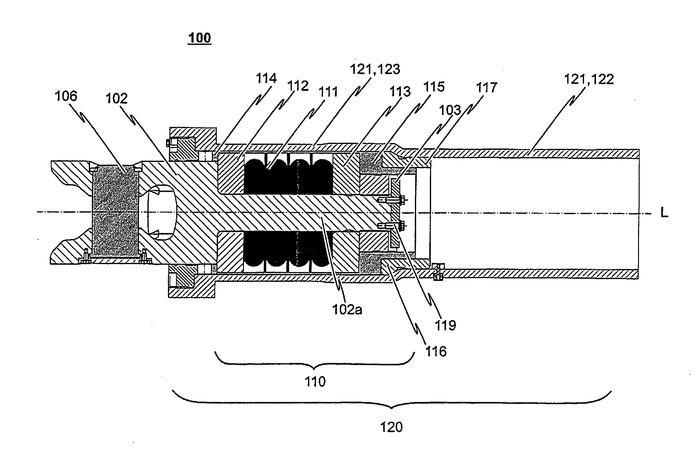
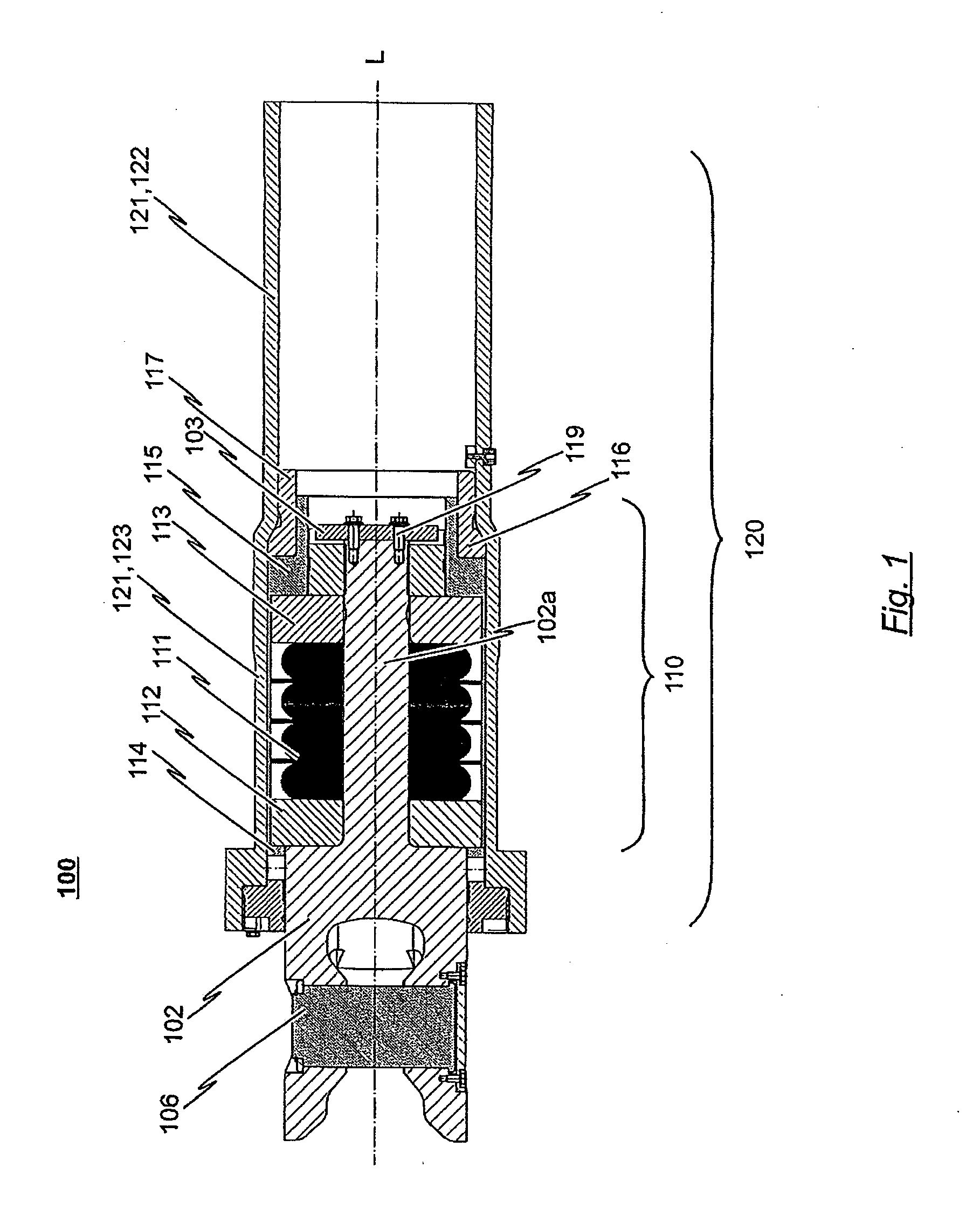
[0013]FIG. 1 schematically depicts a shock absorber 100 of the prior art in a longitudinal sectional view which comprises a drawgear 110 having a regeneratively-designed spring mechanism and a known prior art energy-absorbing device 120 having an irreversible energy-absorbing element 121. The shock absorber 100 depicted schematically in FIG. 1 is integrated into a coupler shank of a central buffer coupling.

[0014]In the embodiment depicted, the drawgear 110 of the...


PUM


Abstract

An energy-absorbing device, particularly for a shock absorber of a track-guided vehicle, has an energy-absorbing element designed as a deformation tube and a counter element which interacts with the deformation tube such that upon a critical impact force being exceeded, the counter element and the deformation tube exhibit a relative movement toward one another while at least a portion of the impact energy introduced into the energy-absorbing device is simultaneously absorbed. For the energy absorbtion to take place according to a predictable sequence of events when force is introduced non-axially into the energy-absorbing device, the counter element is connected to the deformation tube by means of a form-fit connection circumferential to the deformation tube so as to prevent twisting of the counter element relative the deformation tube.

Description

CROSS-REFERENCE TO RELATED APPLICATION[0001]This application claims priority to European Patent Application No. EP 10 172 194.2 filed Aug. 6, 2010 which is herein incorporated by reference.BACKGROUND OF THE INVENTION[0002]1. Field of the Invention[0003]The invention relates to an energy-absorbing device, in particular for a shock absorber of a track-guided vehicle, wherein the energy-absorbing device contains an energy-absorbing deformation tube as well as a counter element. The counter element interacts with the deformation tube such that upon exceeding a critical impact force introduced into the energy-absorbing device, the counter element and the deformation tube realize a relative movement toward one another while at least a portion of the impact energy introduced into the energy-absorbing device is simultaneously absorbed.[0004]2. Background Art[0005]The principle of an energy-absorbing device of the type described above is common knowledge in the prior art and is employed for ...

Claims


Application Information

Patent Timeline
IPC IPC(8): B60R19/26B61G11/00B61D15/06
CPCB60R19/30B60R19/34F16F7/125B61G9/06B61G11/16B60R19/36
Inventor KONTETZKI, ARTHUR
Owner VOITH PATENT GMBH
Learn More