
Gluing mechanism

a gluing mechanism and gluing technology, applied in the direction of manual gluing dispensers, transportation and packaging, packaging, etc., can solve the problems of limited location control of glue applicators, low work efficiency, and difficult operation of the gluing mechanism of prior art, and achieve excellent gluing quality, simple structure of the gluing mechanism, and high working efficiency

Inactive Publication Date: 2012-02-09
CHENG UEI PRECISION IND CO LTD
View PDF3 Cites 39 Cited by
  • Summary
  • Abstract
  • Description
  • Claims
  • Application Information

AI Technical Summary

Benefits of technology

[0007]For solving the drawbacks of prior art, a gluing mechanism has a high working efficiency. The gluing mechanism can proceed a precise rotary gluing process to workpieces. An excellent gluing quality can be realized.
[0009]As aforementioned, on one hand, the gluing mechanism of the present invention only needs one motor to drive multiple turn tables to proceed a rotary gluing process to multiple workpieces. The structure of the gluing mechanism is simple and the gluing mechanism has a high working efficiency; on the other hand, the gluing device of the gluing mechanism can proceed a precise location for the glue applicators in three directions. Therefore, an excellent gluing quality can be obtained.

Problems solved by technology

The gluing mechanism of prior art is not easy for operation and the work efficiency is low.
The location control of the glue applicators has limitation.
The location for the glue applicators is not precise enough and consequently inhibits the gluing quality.

Method used


Image

  • Gluing mechanism
  • Gluing mechanism
  • Gluing mechanism

Examples


Embodiment Construction

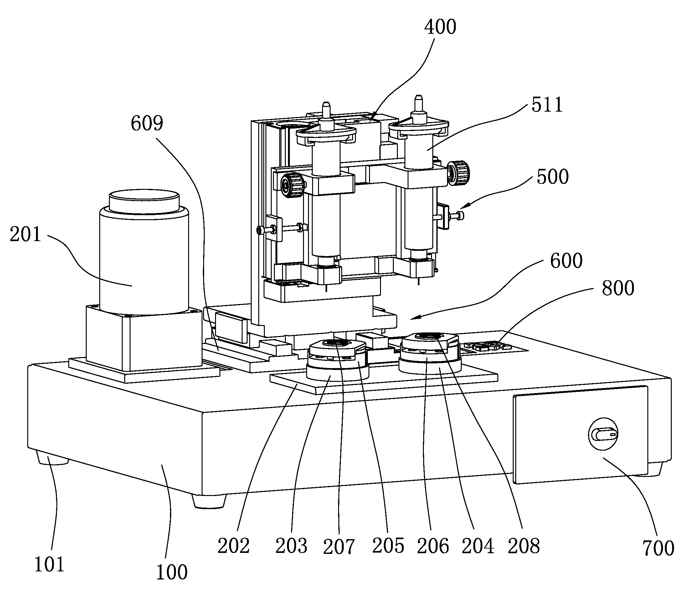
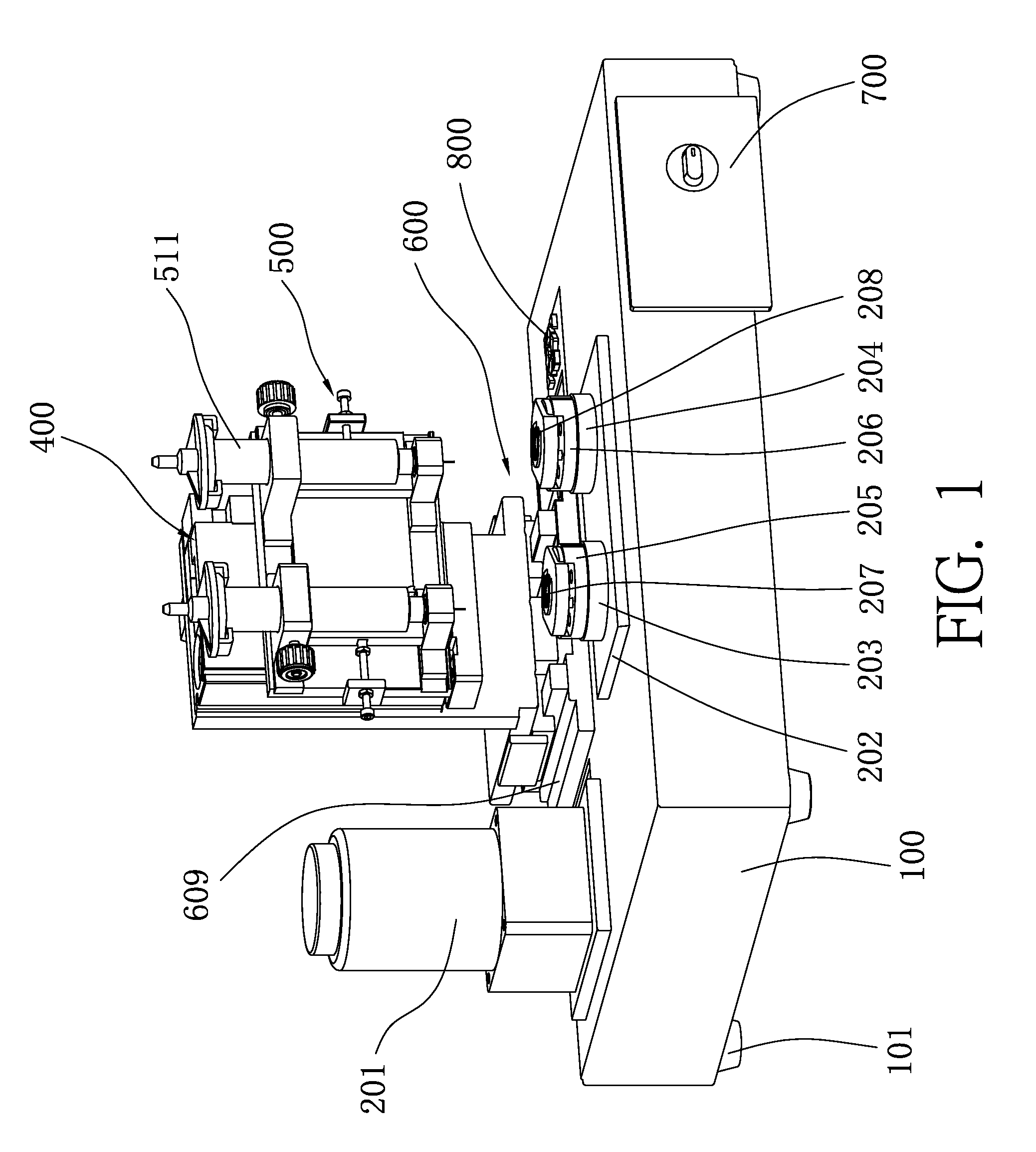
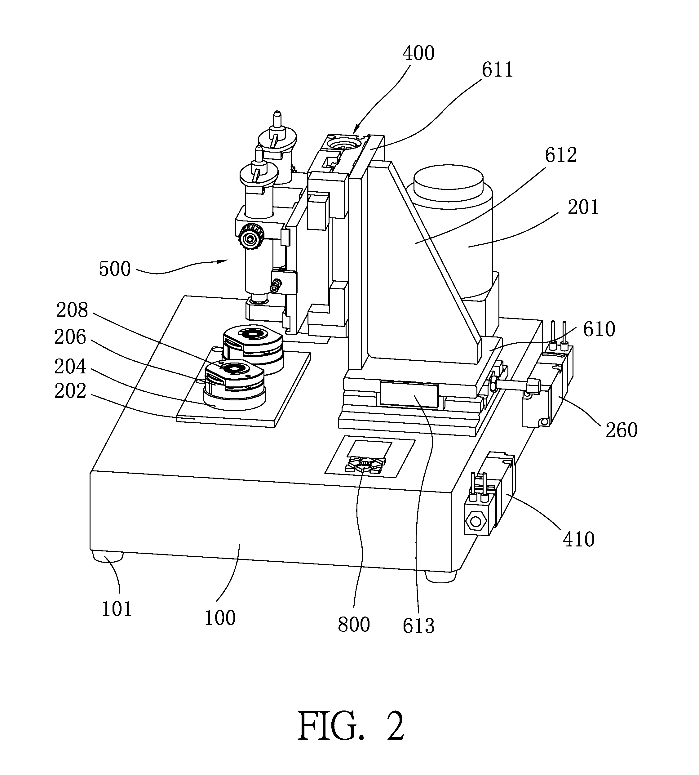
[0016]Please refer to FIG. 1 and FIG. 2. The gluing mechanism of the present invention comprises a platform 100, several supporting legs 101, a motor 201, a turn table fix seat 202, a first turn table 203, a second turn table 204, a first workpiece fix seat, a second workpiece fix seat, a base plate 609, a forward assembly 600, an elevator 400, a panning assembly 500 and two glue applicators 511. In this embodiment, the first workpiece is a first sound membrane 207. The second workpiece is a second sound membrane 208. The first workpiece fix seat is a first sound membrane fix seat 205. The second workpiece fix seat is a second sound membrane fix seat 206. The several supporting legs 101 are installed under the platform 100 for supporting the platform 100.

[0017]The first turn table 203 and the second turn table 204 are firmly installed on the turn table fix seat 202. The motor 201 are jointed with the first turn table 203 and the second turn table 204 for driving the first turn table...


PUM

PropertyMeasurementUnit
structureaaaaaaaaaa
diameteraaaaaaaaaa
pressureaaaaaaaaaa

Abstract

A gluing mechanism comprising a platform, a plurality of turn tables set on the platform for workpieces, a motor for driving the turn tables and a gluing device firmly set up on the platform. The gluing device comprises a forward assembly, an elevator, a panning assembly and a plurality of glue applicators. The forward assembly is set on the platform and moves along a shorter side of the platform. The elevator is set on the forward assembly and moves relative to the platform vertically. The panning assembly is set on the elevator and moves along a longer side of the platform. The glue applicators are installed on the panning assembly. The motor drives the turn tables simultaneously. The gluing mechanism of the present invention has benefits of simple structure, a high working efficiency and proceeds a precise rotary gluing process to workpieces. Therefore, an excellent gluing quality can be realized.

Description

BACKGROUND OF THE INVENTION[0001]1. Field of the Invention[0002]The present invention generally relates to a gluing mechanism, and more particularly to a gluing mechanism having multiple glue applicators.[0003]2. Description of Prior Art[0004]In a traditional rotary gluing process, two sets of platforms are generally utilized for promoting the working efficiency. Each set of platform is equipped one set of gluing device to independently proceed the gluing process respectively. Each set of gluing device comprises a turn table fixed on the platform, a motor for driving the turn table, a glue applicator above the turn table, a glue applicator fixe seat for installing the glue applicator and an elevator installed on the glue applicator fixe seat for moving the glue applicator vertically.[0005]During the gluing process of such a dual-head gluing mechanism, two motors drive the corresponding turn tables respectively to rotate the workpieces on the turn tables in the beginning. Then, two e...

Claims


Application Information

Patent Timeline
Patent Type & Authority Applications(United States)
IPC IPC(8): B05C1/02
CPCB05C5/0208B05C5/0225Y10T156/1798B05C11/1044B05C13/02B05C5/027
Inventor WU, PEI-CHENGLEE, FENG-CHICHIU, KUO-CHUANLIAO, CHIA-HSIN
Owner CHENG UEI PRECISION IND CO LTD
Learn More