Oven door

a technology for ovens and doors, applied in the field of oven doors, can solve the problems of increasing the cost of exterior panels formed of stainless steel, increasing the cost of metal components and glass pane manufacturing, and relatively high material cost for manufacturing metal components and glass panes, etc., and achieves the effects of less cost, less material cost, and less cost of material and frame parts

Inactive Publication Date: 2012-02-09
BASF AG
View PDF7 Cites 21 Cited by
  • Summary
  • Abstract
  • Description
  • Claims
  • Application Information

AI Technical Summary

Benefits of technology

[0012]By forming the frame portion of the exterior panel from plastic, the costs associated with material and manufacturing of the frame portion is advantageously decreased. The manufacturing process of forming the frame portion is more efficient, and thus less costly, by decreasing or eliminating secondary assembly steps. Forming the exterior from plastic also allows the designer more styling freedom because plastic is relatively easy to form into intricate shapes. The plastic of the exterior panel also provides superior insulation to reduce the amount of heat that is transferred to the an exterior side of the exterior panel.
[0013]In addition, the plastic of the frame portion can be advantageously colored. Further, since the plastic is colored, as opposed to being painted, desired coloring of the frame portion is accomplished without secondary steps such as painting, thereby advantageously making the manufacturing process of the exterior panel more efficient and less costly. In addition, since the plastic itself is colored, the coloring is more durable than paint.
[0014]Finally, the interaction between the handle and the exterior panel advantageously increases the stability and durability of the oven door. By receiving the boss portion in the pocket, the exterior panel firmly retains the handle to increase the stability of the handle relative to the exterior panel. Also, since the bottom is disposed between the boss portion and the handle and since the post extends from the handle, the bottom of the exterior panel is retained between the handle and the interior panel when the post is connected to the interior panel. As such, the interior panel, the exterior panel, and the handle are coupled together when the post is connected to the interior panel.

Problems solved by technology

The material cost for manufacturing the metal components and the glass pane is relatively high.
In addition, relatively high manufacturing costs are associated with forming the components and the glass panel separately and subsequently assembling the components and the glass panel.
As such, the exterior panel can be formed of stainless steel to provide this appearance; however, stainless steel is a relatively expensive material thereby increasing the cost to manufacture exterior panels formed of stainless steel.
Such paint adds cost not only for the paint itself but also for manufacturing costs associated with applying the paint to the exterior panel.
The paint is also subject to scratching, chipping, cracking, etc.
As the handle is used over time, the interface between the abutting flat surfaces of the handle and the exterior panel begins to loosen such that the handle wobbles relative to the exterior panel.
Such an occurrence gives an unwanted feel and appearance of low quality.

Method used


Image

  • Oven door
  • Oven door
  • Oven door

Examples


first embodiment

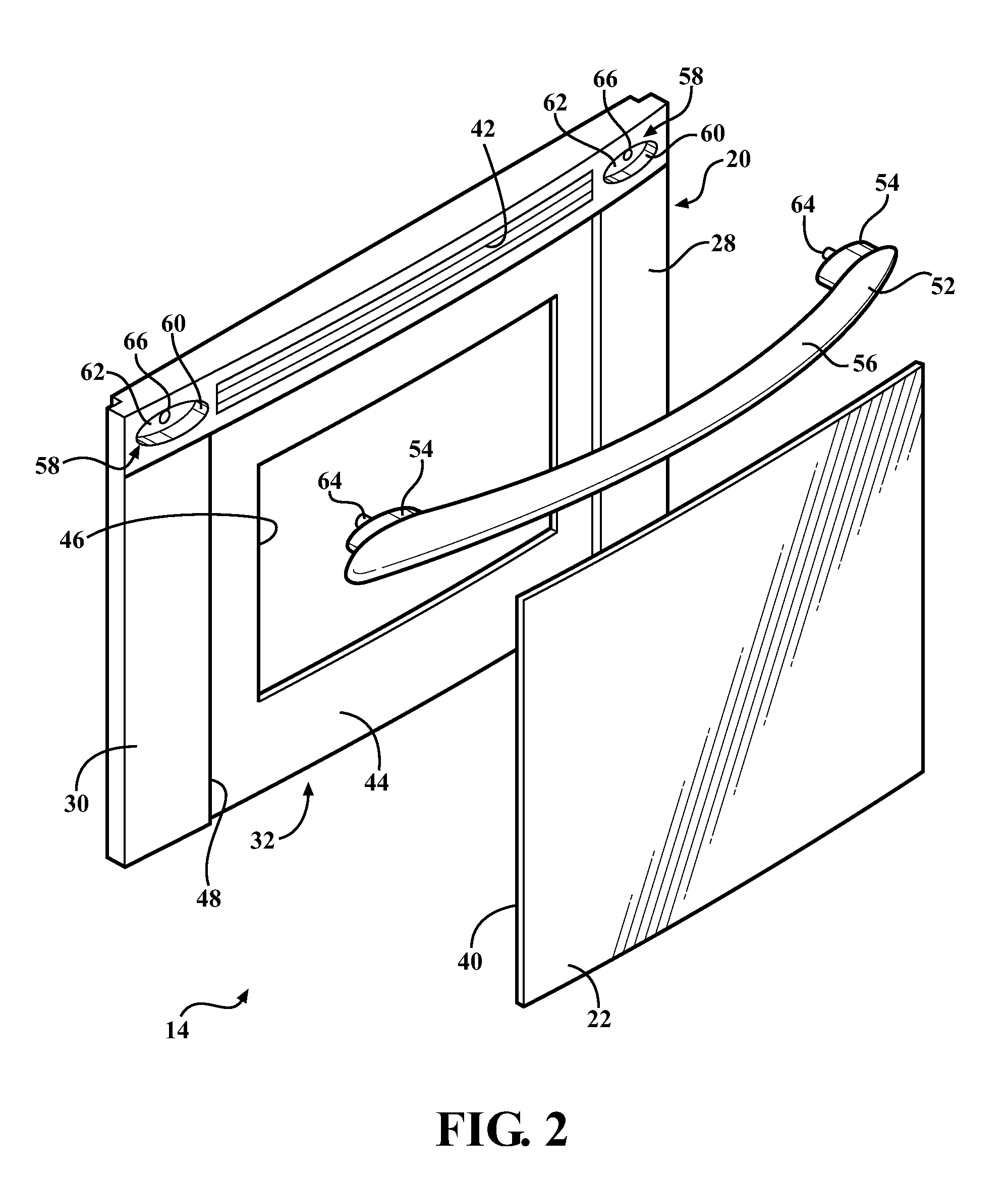
[0033]In the first oven door 14, with reference to FIGS. 2 and 3, the exterior panel 20 has a masking portion 44 typically formed of plastic. The masking portion 44 is typically integrally formed with the frame portion 30 as shown in FIGS. 2 and 3, i.e., formed together simultaneously or at substantially the same time so as to form a single part. Alternatively, the masking portion 44 is integrally formed with the non-opaque panel 22 such that the masking portion 44 and the non-opaque panel 22 in combination are assembled to the frame portion 30 in the aperture 32. In any event, the masking portion 44 extends from the frame portion 30 into the aperture 32 along the inside surface 40 of the non-opaque panel 22 and defines a window 46 for viewing the heating chamber 12 through the glass sheet of the interior panel 18.

[0034]The masking portion 44 is typically formed of the same type of plastic as the rest of the exterior panel 20 as set forth above. However, it should be appreciated tha...

second embodiment

[0041]With reference to FIG. 4, in the first oven door 14, the non-opaque panel 22 is integrally formed with the exterior panel 20, i.e., formed together simultaneously or at substantially the same time so as to form a single part. The non-opaque panel 22 is typically formed of plastic. The non-opaque panel 22 can be formed from the same type of plastic as that of the exterior panel 20 or can be formed from a different type of plastic than that of the exterior panel 20. The plastic can be glass filled or can be free of glass filling. One example of a type of suitable plastic for the non-opaque panel 22 is an unfilled polyethersufone commercially available from BASF Corporation in Florham Park, NJ under the tradename Ultrason® E2010. However, it should be appreciated that the non-opaque panel 22 can be formed of any type of suitable material without departing from the nature of the present invention.

[0042]In the second embodiment of the first oven door 14, the masking portion 44 can ...


PUM


Abstract

An oven door includes an interior panel and an exterior panel. The interior panel faces the heating chamber and has a glass sheet for viewing the heating chamber. The exterior panel is affixed to the interior panel and includes a frame portion formed of plastic defining an aperture aligned with the glass sheet for viewing the heating chamber. A non-opaque panel is fixed relative to the frame portion and extends across the aperture. The non-opaque panel has an inside surface facing the interior panel and the exterior panel has a masking portion formed of plastic and integrally formed with the frame portion. The masking portion extends from the frame portion into the aperture along the inside surface of the non-opaque panel and defines a window for viewing the heating chamber through the glass sheet.

Description

CROSS-REFERENCE TO RELATED APPLICATIONS[0001]The subject patent application claims priority to and all the benefits of U.S. Provisional Patent Application No. 61 / 371,074 which was filed on Aug. 5, 2010, the entire specification of which is expressly incorporated herein by reference.BACKGROUND OF THE INVENTION[0002]1. Field of the Invention[0003]The present invention relates to an oven door including an exterior panel formed of plastic.[0004]2. Description of the Related Art[0005]An oven door includes an interior panel for sealing a heating chamber of the oven and an exterior panel spaced from the interior panel to provide a layer of insulation, e.g., solid and / or air, between the interior panel and the exterior panel. The exterior panel also aesthetically covers the interior panel.[0006]The exterior panel is typically formed of several metal components that are separately formed and subsequently assembled together. The exterior panel also typically includes a glass pane for viewing ...

Claims


Application Information

Patent Timeline
Patent Type & Authority Applications(United States)
IPC IPC(8): F24C15/04
CPCF24C15/045F24C15/04
Inventor MCMASTER, WILLIAM J.JEWELL, GAVIN L.MURPHY, DAVID J.
Owner BASF AG
Why Eureka
Try Eureka