Delay line structure

a delay line and structure technology, applied in delay lines, waveguides, electrical equipment, etc., can solve the problems of limited utilization and misinterpretation of digital signals at voltage levels, and achieve the effect of avoiding crosstalk noise disturbance and reducing the size of the delay lin

Inactive Publication Date: 2012-02-09
CHUNG YUAN CHRISTIAN UNIVERSITY
View PDF3 Cites 6 Cited by
  • Summary
  • Abstract
  • Description
  • Claims
  • Application Information

AI Technical Summary

Benefits of technology

[0016]When compared with the delay line in prior art, which is not installed with grounding guard traces, the present invention avoids the crosstalk noise disturbance by means of the first grounding guard trace and the second grounding guard trace connecting to the ground with an end. When compared with the serpentine delay line having a guard trace with both ends connecting to the ground in prior art, since there is no need to install the via inside the serpentine delay line according to an embodiment of the present invention, the problem of being unable to downsize the serpentine delay line is easily solved.

Problems solved by technology

Usually the requirement of synchronizing signals is met by increasing delay time with a delay line.
However, bending the delay line forms several coupling line segments in the delay line itself, also generates crosstalk noise disturbance and further affects a signal waveform received, which leads to misinterpretation on a voltage level of a digital signal.
Meanwhile, since the guard trace 12 and 13 with two ends connecting to the ground can merely be utilized in a structure of microstrip line, the utilization is still limited.

Method used


Image

  • Delay line structure
  • Delay line structure
  • Delay line structure

Examples


Embodiment Construction

[0025]The present invention relates to a delay line structure, and more particularly to a serpentine delay line structure with grounding guard traces. In the following description, numerous details are set forth in order to provide a thorough understanding of the present invention. It will be appreciated by one skilled in the art that variations of these specific details are possible while still achieving the results of the present invention. In other instance, well-known components are not described in detail in order not to unnecessarily obscure the present invention.

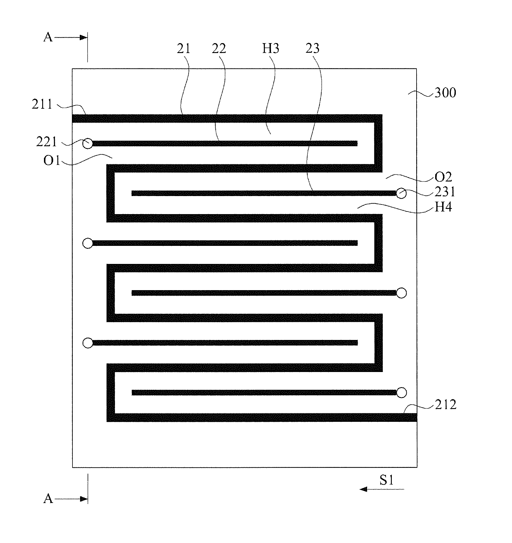
[0026]Referring to FIG. 3 and FIG. 4, wherein FIG. 3 is the upper view of an embodiment of a serpentine delay line structure having grounding guard trace according to of the present invention while; FIG. 4 shows the cross-sectional view of a strip line of the serpentine delay line according to the present invention taken along the A-A line in FIG. 3. A delay line structure is disposed on a substrate 300. The substrate...


PUM


Abstract

A delay line structure includes a serpentine delay line, a first grounding guard trace and a second grounding guard trace. The serpentine delay line is disposed in a layout layer of a substrate in a manner of extending from an input end to an out put end in serpentine so as to form at least a first coupling area having a first opening toward a first direction and at least a second coupling area having a second opening toward a direction opposite to the first direction. The first grounding guard trace is disposed in the layout layer in a manner of extending from the first opening toward the first coupling area and an end of the first grounding guard trace close to the first opening is electrically connected to the grounding circuit through a first via. The second grounding guard trace is disposed in the layout layer in a manner of extending from the second opening toward the second coupling area and an end of the second grounding guard trace close to the second opening is electrically connected to the grounding circuit through a second via.

Description

[0001]This application claims the benefits of the Taiwan Patent Application Serial NO. 099125912 filed on Aug. 4, 2010, the subject matter of which is incorporated herein by reference.BACKGROUND OF THE INVENTION[0002]1. Field of the Invention[0003]The present invention relates to a delay line structure, and more particularly to a serpentine delay line structure with grounding guard traces.[0004]2. Description of the Prior Art[0005]Signal synchronizing is always a concern when it comes to the high speed digital signal. Usually the requirement of synchronizing signals is met by increasing delay time with a delay line.[0006]To save space, the delay line is usually bent. There are various delay lines, among which a serpentine delay line is very common. Referring to FIG. 1, FIG. 1 illustrates a delay line structure in prior art. A serpentine delay line 11 is bent repeatedly and arranged on a substrate 100.[0007]However, bending the delay line forms several coupling line segments in the d...

Claims


Application Information

Patent Timeline
Patent Type & Authority Applications(United States)
IPC IPC(8): H01P1/18
CPCH01P9/006
Inventor SHIUE, GUANG-HWACHIU, PO-WEI
Owner CHUNG YUAN CHRISTIAN UNIVERSITY
Why Eureka
Try Eureka