Handwriting input device
a handwriting input and input device technology, applied in the field of handwriting input devices, can solve the problems of incomplete loss of input information, difficult to use the electronic blackboard-type handwriting input devices, and inability to recognize letters or figures written or drawn on white sheets or whiteboards in dark places, so as to prevent the loss of input information
- Summary
- Abstract
- Description
- Claims
- Application Information
AI Technical Summary
Benefits of technology
Problems solved by technology
Method used
Image
Examples
first exemplary embodiment
[0043]Next, a first exemplary embodiment of the present invention will be described in detail with reference to the drawings.
[0044][Description of Configuration]
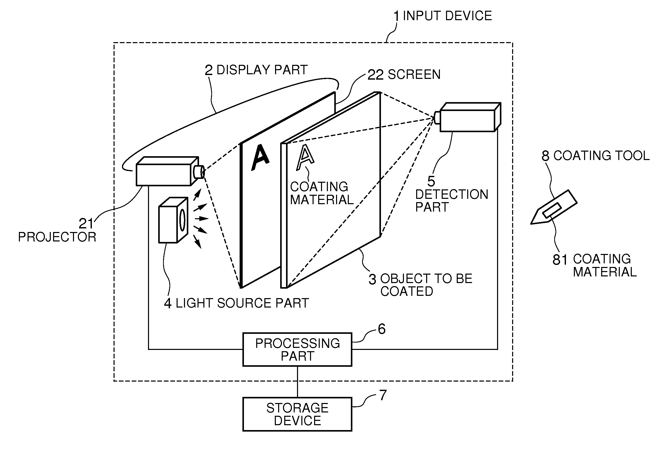
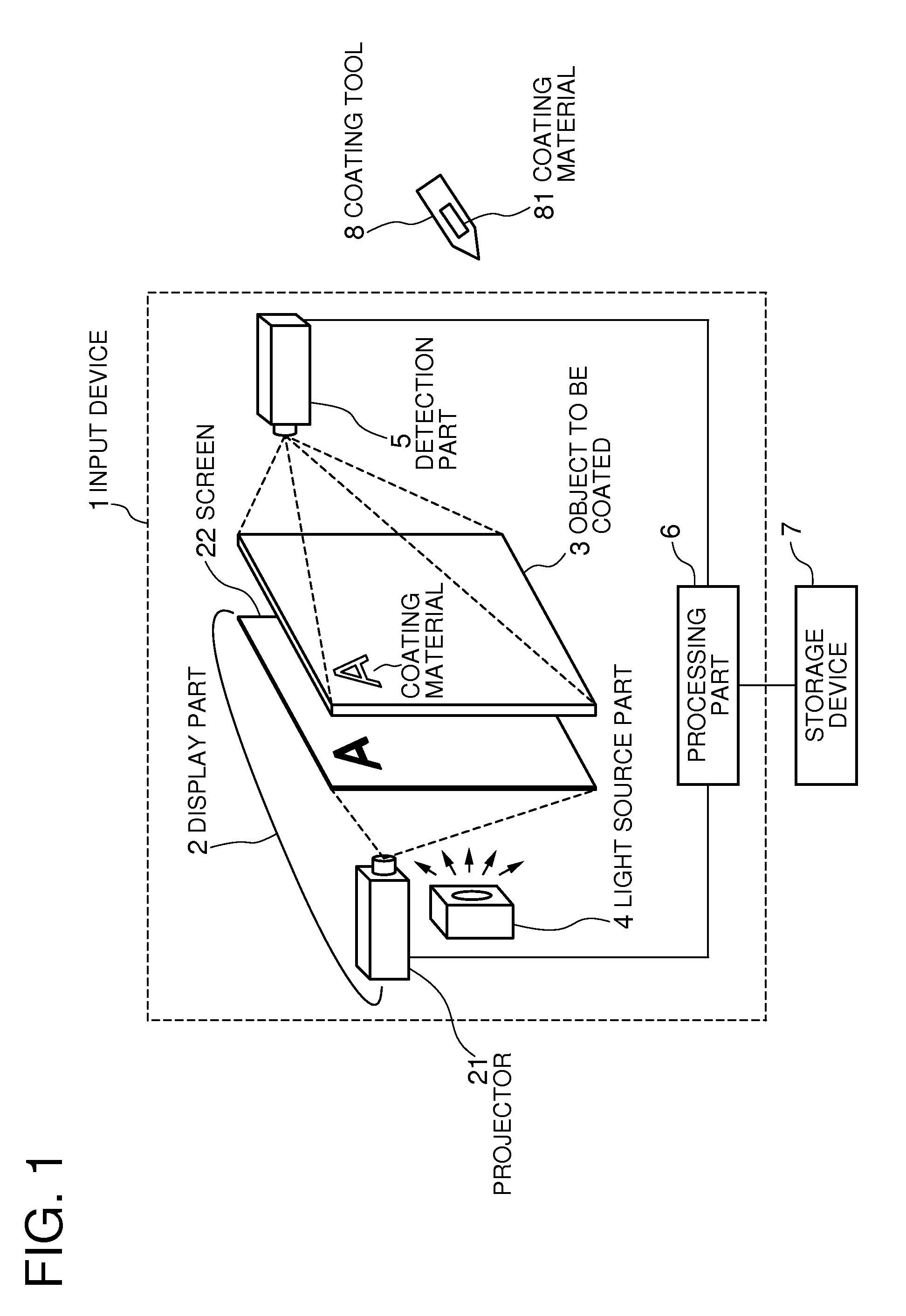
[0045]With reference to FIG. 1, an input device 1 of the present invention is connected to a storage device 7, and is configured by a display part 2 configured by a projector 21 and a screen 22, an object to be coated 3 to and from which a coating material is attached and removed, a light source part 4, a detection part 5, and a processing part 6.
[0046]The projector 21 projects an image inputted by the processing part 6 onto the screen 22. A general liquid-crystal projector can be used as the projector 21, and a resin film that diffuses light can be used as the screen 22.
[0047]The object to be coated 3 is a transparent plane board to and from which a coating material can be attached and wiped off, for example, a thin plastic board. The drawing shows the screen 22 and the object to be coated 3 separated from each other, but a...
second exemplary embodiment
[0080]As a second exemplary embodiment of the present invention, a configuration in which a basic configuration is as described above but the arrangement of the light source part of the input device 1a, the configuration of the display part and the property of the coating material are different from those of the first exemplary embodiment will be described in detail with reference to the drawings.
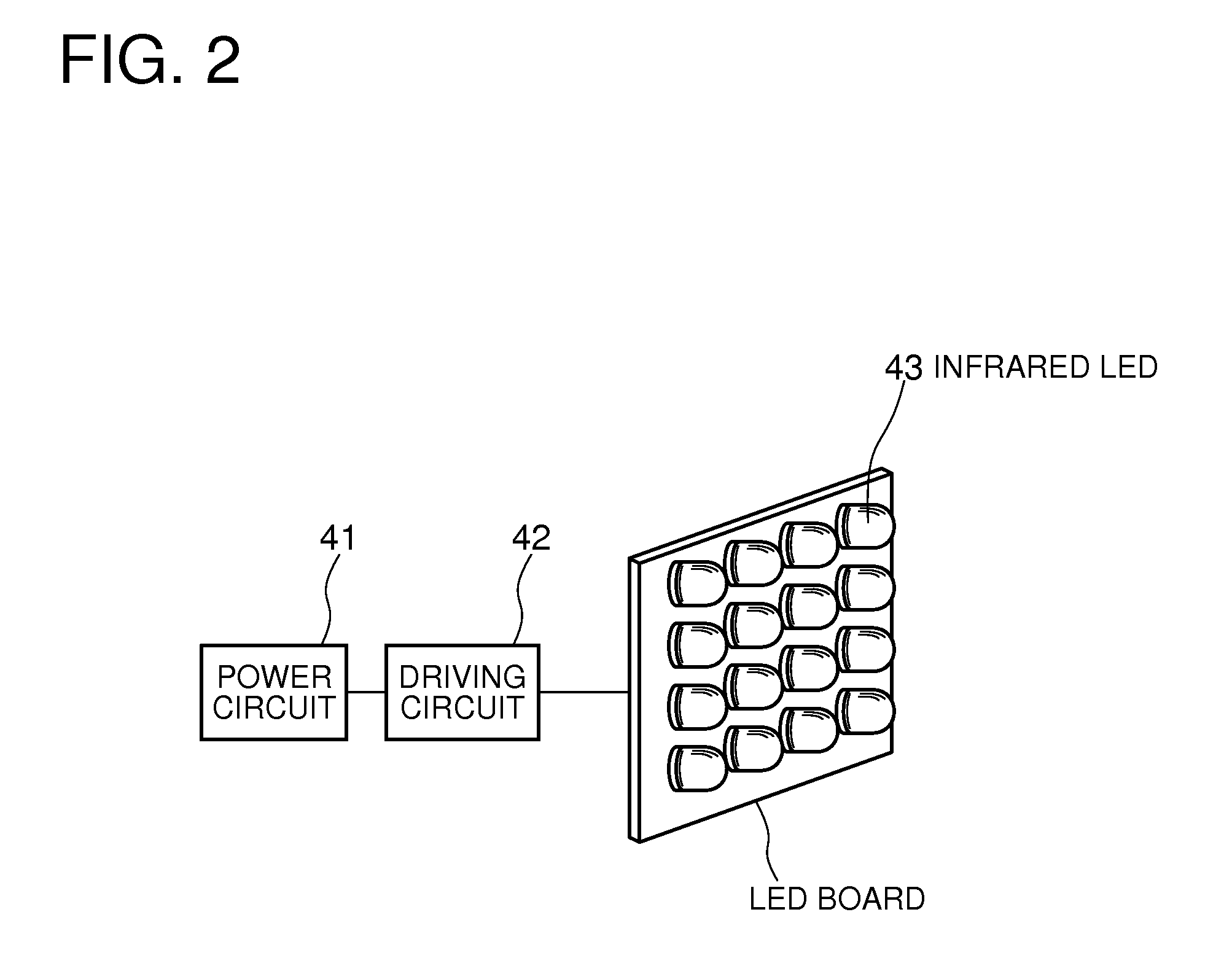
[0081]With reference to FIG. 10, a light source part 4a emits light except the visible light so as to enter from the side face of the object to be coated 3. In the light source part 4a, for example, one or more infrared emitting diodes (LED) 44 arranged in line and driven by the power circuit 41 and the driving circuit 42 can be used. The light source part 4a may be placed on one side of the object to be coated 3, or may be placed on a plurality of sides. FIG. 10 shows an example that the light source parts 4a are placed in two places, above and below the object to be coated 3.
[0082]A displ...
third exemplary embodiment
[0089]As a third exemplary embodiment of the present invention, a configuration in which a basic configuration is as described above but the configurations of the light source part and the detection part of an input device 1 b are different from those of the exemplary embodiments described above will be described in detail with reference to the drawings.
[0090]With reference to FIG. 16, the display part is a flat panel display using the liquid crystal technique, and is integrated with the detection part. A light source part 4b is a backlight of this flat panel display, and generates both visible light and light except the visible light. As in the second exemplary embodiment, the optical material contained in the coating material 81 is a material that is substantially transparent (or translucent) with respect to visible light but reflects light except the visible light generated by the light source part 4b.
[0091]FIG. 17 is a block diagram showing an example of a configuration of the ...
PUM
 Abstract
Description
Claims
Application Information
 - R&D
- Intellectual Property
- Life Sciences
- Materials
- Tech Scout
- Unparalleled Data Quality
- Higher Quality Content
- 60% Fewer Hallucinations
Browse by: Latest US Patents, China's latest patents, Technical Efficacy Thesaurus, Application Domain, Technology Topic, Popular Technical Reports.
© 2025 PatSnap. All rights reserved.Legal|Privacy policy|Modern Slavery Act Transparency Statement|Sitemap|About US| Contact US: help@patsnap.com


