Vibration applying structure detecting device and vehicle control device

a technology of structure detection and vibration, applied in the direction of cycle equipment, television systems, instruments, etc., can solve the problems of erroneously detecting vibration caused by bumps and dips other than rumble strips, and achieve the effect of accurately detecting the fact that the vehicle is erroneously detecting vibration

Inactive Publication Date: 2012-02-09
NISSAN MOTOR CO LTD
View PDF4 Cites 17 Cited by
  • Summary
  • Abstract
  • Description
  • Claims
  • Application Information

AI Technical Summary

Benefits of technology

[0014]According to the present invention, since the frequency threshold value and / or amplitude threshold value used for judging that the wheels of the vehicle are contacting rumble strips are set such that the values are smaller in the case when it is judged that there is a lane departure tendency than in the case when it is judged that there is no lane departure tendency, when a lane departure tendency occurs, the frequency threshold value or the amplitude threshold value can be set at a larger value to prevent erroneously detecting vibration caused by bumps and dips other than rumble strips as vibration caused by rumble strips. Thus, when there is a lane departure tendency, it is possible to accurately detect the fact that the vehicle is contacting a vibration applying structure such as rumble strips.

Problems solved by technology

However, vibration caused by bumps and dips on a road surface other than rumble strips is also input into a travelling vehicle.
As a result, the vibration caused by bumps and dips other than rumble strips may be erroneously detected as vibration caused by rumble strips.

Method used


Image

  • Vibration applying structure detecting device and vehicle control device
  • Vibration applying structure detecting device and vehicle control device
  • Vibration applying structure detecting device and vehicle control device

Examples


second embodiment

[0166]

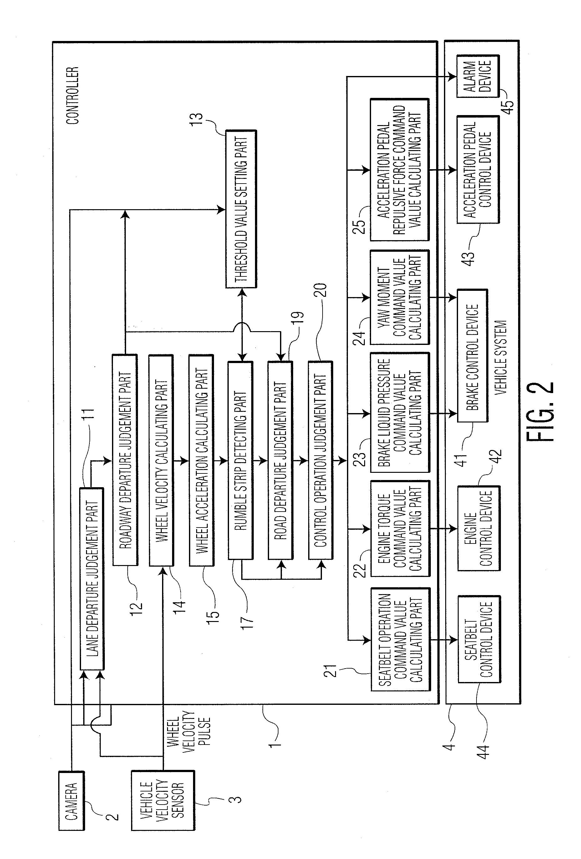
[0167]In the aforementioned embodiment, the threshold value setting part 13 changes the frequency threshold value. That is, when it is found that there is a roadway departure tendency (or lane departure tendency), the frequency threshold value is set at a smaller value. The threshold value used for detecting rumble strips and set by the threshold value setting part 13 can also be an amplitude threshold value instead of a frequency threshold value. In other words, when it is found that there is a roadway departure tendency (or lane departure tendency), the amplitude threshold value (that is, threshold value A in FIG. 23) is reduced. When it is judged that there is no roadway departure tendency (or lane departure tendency), the amplitude threshold value (that is, threshold value A in FIG. 23) is increased. In this way, the same effect as that of the first embodiment can be realized. The rest of the configuration is the same as that used for setting the frequency threshold value ...


PUM


Abstract

A vibration applying structure detecting device for a wheeled vehicle traveling on a roadway having a vibration applying structure on a road surface in or adjacent to the roadway includes a lane departure judgment device that determines whether there is a lane departure tendency, a vibration detecting device that determines the frequency and the amplitude of input vibration from a road surface to the vehicle, and a contact judgment device that determines that at least one of the wheels of the vehicle is contacting the vibration applying structure when the input vibration with an amplitude equal to or greater than a prescribed amplitude threshold value has a frequency that is equal to or greater than a prescribed frequency threshold value. The device may also include a threshold value setting device that sets one or both of the amplitude threshold value and the frequency threshold value.

Description

CROSS-REFERENCE TO RELATED APPLICATIONS[0001]This application claims priority under 35 U.S.C. §119 to Japanese Patent Application No. 2010-178931, filed on Aug. 9, 2010, which is incorporated by reference herein in its entirety.BACKGROUND OF THE INVENTION[0002]1. Field of Invention[0003]The present invention relates to a vibration applying structure detecting device, which can detect a vibration applying structure formed on a roadway, and a vehicle control device equipped with such a vibration applying structure detecting device.[0004]2. Description of Related Art[0005]Conventionally, technology is known as a technology for detecting when vehicle wheels contact rumble strips as a vibration applying structure. The rumble strips are bumps and dips provided on the road surface along the travel lane at the edge of the travel lane. The amplitude and frequency of the vibration input into the vehicle are detected. Based on that amplitude and frequency of vibration, when it is determined th...

Claims


Application Information

Patent Timeline
Patent Type & Authority Applications(United States)
IPC IPC(8): B60G17/016H04N7/18G01M17/00G06F19/00B60G17/018
CPCB60K26/021B60W10/06B60W2720/14B60W30/12B60W2520/28B60W10/18
Inventor NAKAMURA, MASAHIDEMINEGISHI, KOUKI
Owner NISSAN MOTOR CO LTD
Why Eureka
Try Eureka