
Method for determining at least one geometric postural parameter when fitting a corrective spectacle frame on the face of a wearer in the anatomical posture thereof

Active Publication Date: 2012-02-09
ESSILOR INT CIE GEN DOPTIQUE
View PDF1 Cites 14 Cited by
  • Summary
  • Abstract
  • Description
  • Claims
  • Application Information

AI Technical Summary

Benefits of technology

[0023]Thus, by selecting an anatomical plane of orientation relative to Frankfurt's plane that is close to a known value that is statistically determined for a given population of individuals, the orientation of said anatomical plane in the anatomical posture of the wearer can easily be determined.
[0025]The accuracy with which the geometrical-and-postural parameters are determined in this way is increased, thereby enabling ophthalmic correcting lenses to be fitted more accurately to the selected frame and optimizing wearer comfort.
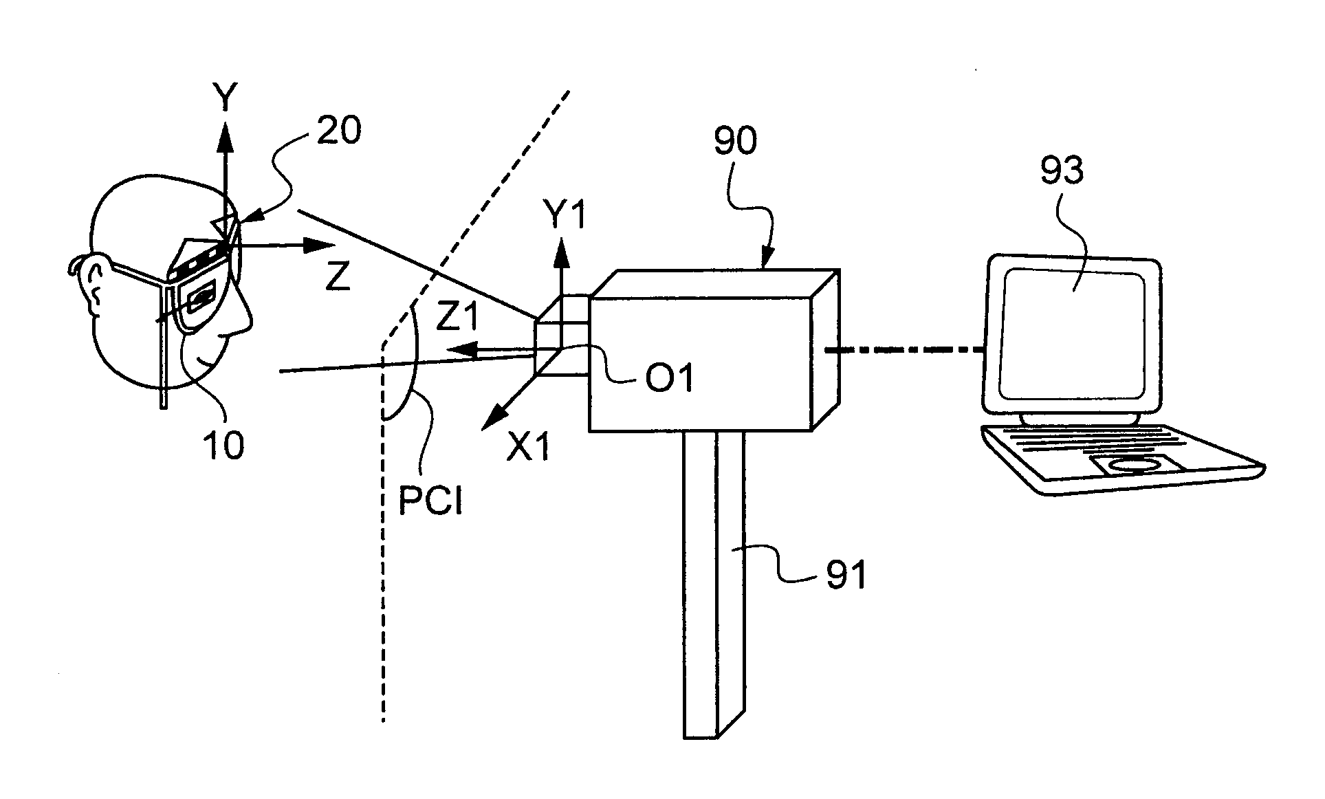
[0038]By way of example, the position-identification device is in the form of an accessory that can easily be clipped onto the wearer's eyeglass frame or that can be fitted onto the wearer's head. Using an image of such a device, it is possible to fully determine its position and orientation relative to the image-capture device.

Problems solved by technology

Nevertheless, those methods of determining the geometrical-and-postural parameters of the wearer, regardless of whether they are manual or automated, suffer from considerable inaccuracy.
Unfortunately, for reasons of speed of execution and of comfort for the optician and for the wearer, the position of the wearer's head while taking the image is not monitored.
However, if the angle of inclination of the head in its sagittal plane departs from the anatomical posture by 1 degree, there will be an error of 1 degree in the measurement of the pantoscopic angle and an error of 0.5 millimeters in the measurement of the heights of the eyes.

Method used


Image

  • Method for determining at least one geometric postural parameter when fitting a corrective spectacle frame on the face of a wearer in the anatomical posture thereof
  • Method for determining at least one geometric postural parameter when fitting a corrective spectacle frame on the face of a wearer in the anatomical posture thereof
  • Method for determining at least one geometric postural parameter when fitting a corrective spectacle frame on the face of a wearer in the anatomical posture thereof

Examples


Embodiment Construction

[0055]The following description with reference to the accompanying drawings that are given by way of non-limiting example shows clearly what the invention consists in and how it can be reduced to practice.

[0056]In the accompanying drawings:

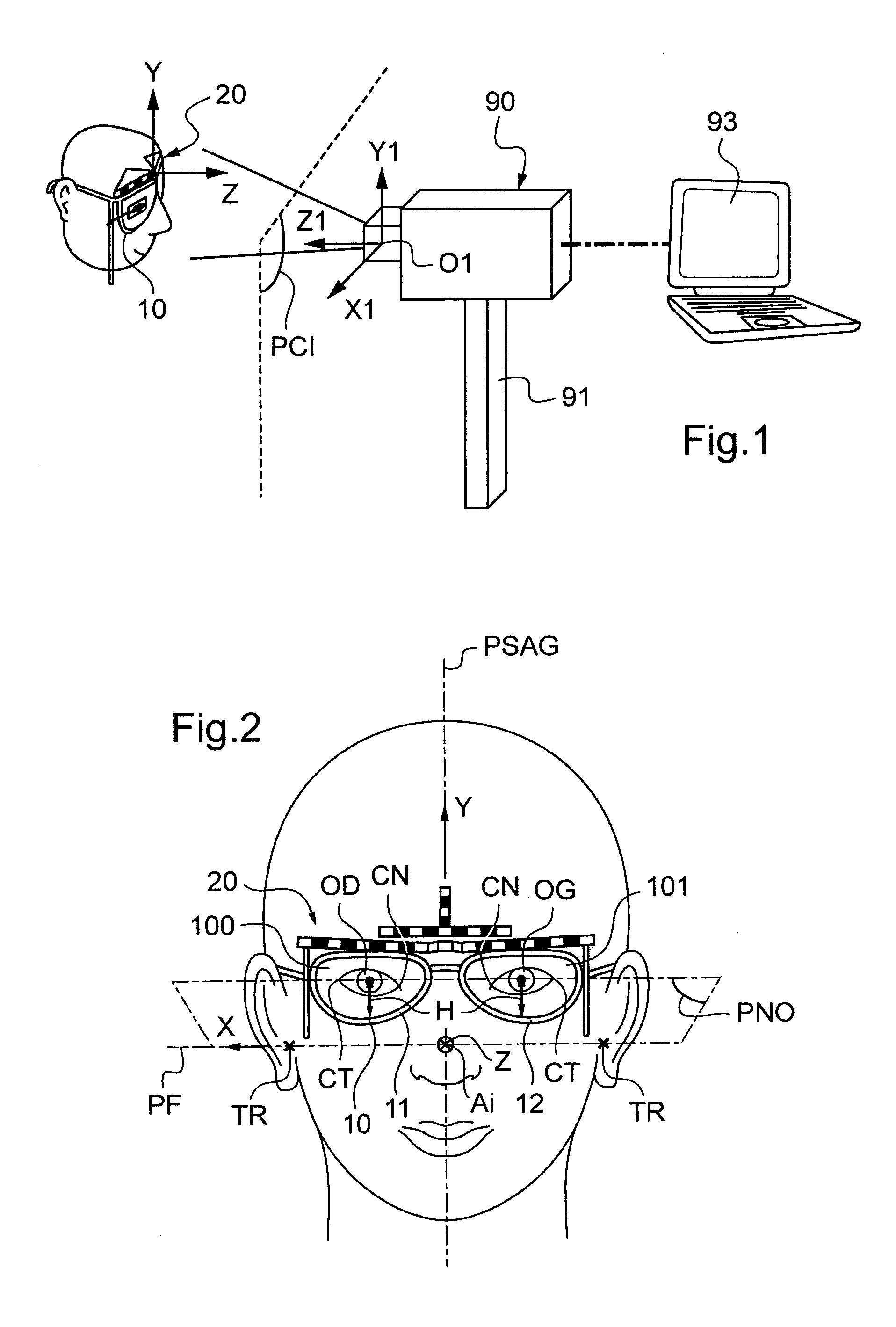
[0057]FIG. 1 is a perspective view of the FIG. 2 position-identification device fastened on the pair of presentation eyeglasses and of an image-capture device in communication with a processor and calculation system;

[0058]FIG. 2 is a face view of the head of a wearer in the anatomical posture and wearing presentation eyeglasses and a position-identification device;

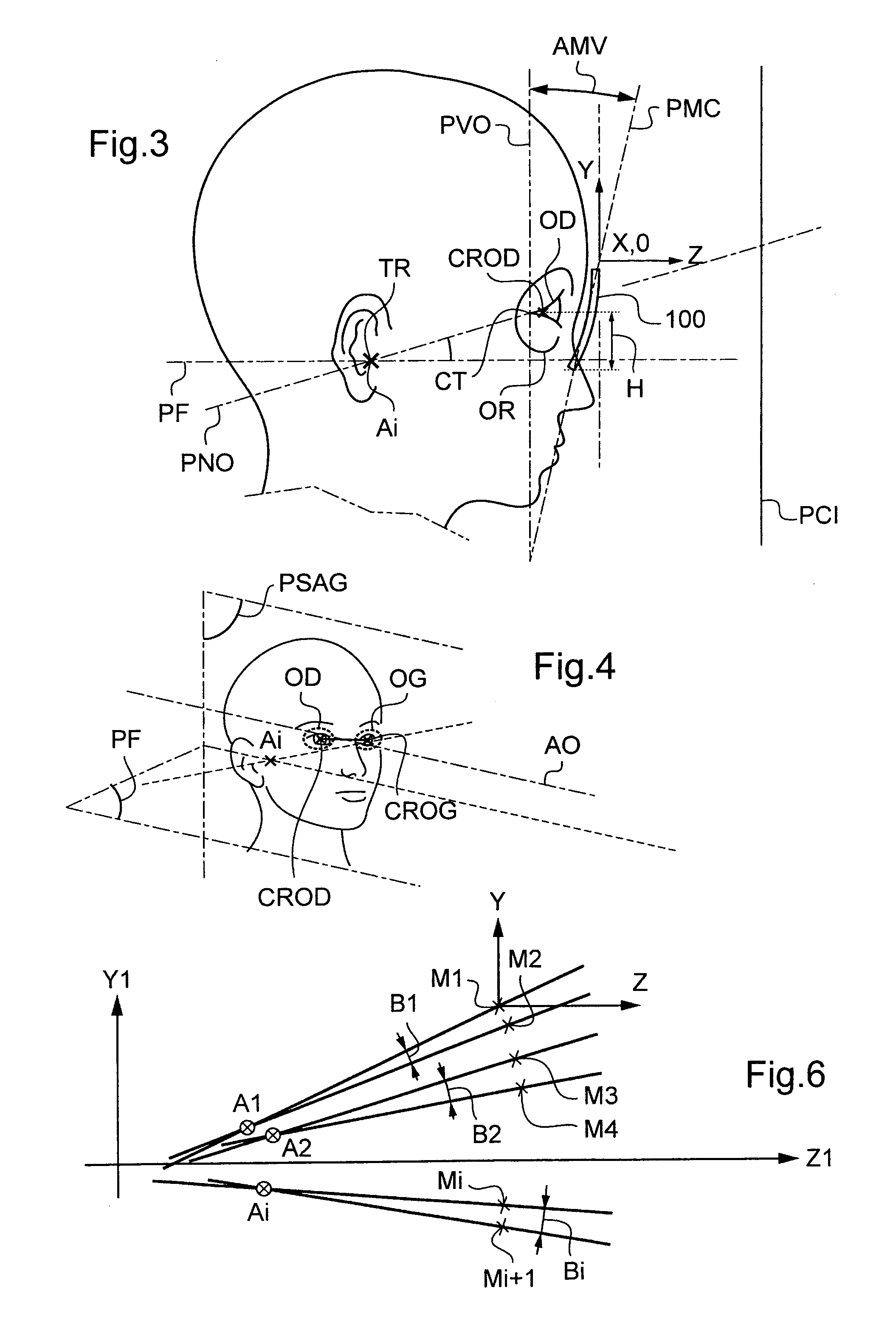
[0059]FIG. 3 is a profile view of the head of a wearer in the anatomical posture and wearing presentation eyeglasses and a position-identification device;

[0060]FIG. 4 is a perspective view of the head of a wearer in the anatomical posture;

[0061]FIG. 5 is a face view of the position-identification device of FIG. 2;

[0062]FIG. 6 is a diagrammatic view relating to the step of determining the...


PUM


Abstract

A method includes:a) defining position-identification elements for identifying the position of a first frame of reference associated with a wearer's head in a second frame of reference associated with an image-capture device and for identifying the angle of inclination of the first frame of reference in the sagittal plane of the wearer's head about a center of rotation of the head;b) capturing a series of at least two images of the wearer's head;c) determining, in the second frame of reference, a position of the center of rotation;d) identifying, in each image, the image of a first anatomical point of the wearer's face;e) determining, in each image, the angle of inclination relative to a reference plane of an anatomical plane that is perpendicular to the sagittal plane and that contains the center of rotation and the first anatomical point;f) comparing the angle with a predetermined value; andg) determining the geometrical-and-postural parameter as a function of the comparison.

Description

TECHNICAL FIELD TO WHICH THE INVENTION RELATES[0001]The present invention relates to a method of determining at least one geometrical-and-postural parameter for placing a frame of vision-correcting eyeglasses on the face of a wearer in the anatomical posture.TECHNOLOGICAL BACKGROUND[0002]In the context of mounting vision-correcting ophthalmic lenses in an eyeglass frame, it is presently preferred to take best account of individual geometrical-and-postural parameters associated with the wearer and the frame selected by the wearer, which parameters are referred to as personalized optical design parameters.[0003]The looked-for geometrical-and-postural parameters are associated both with the shapes of the wearer's head and of the selected eyeglass frame, and also with the wearer's posture. They comprise in particular the three-dimensional configuration of each lens relative to the wearer's head under wearing conditions. This three-dimensional configuration is determined in particular by...

Claims


Application Information

Patent Timeline
IPC IPC(8): A61B3/10
CPCA61B3/11G02C13/005
Inventor CHAUVEAU, JEAN-PIERREBARANTON, KONOGANPEDRONO, CLAUDE
Owner ESSILOR INT CIE GEN DOPTIQUE
Learn More