

Motor control center and bus assembly therefor
- Summary
- Abstract
- Description
- Claims
- Application Information
AI Technical Summary
Benefits of technology
Problems solved by technology
Method used
Image

Examples
Embodiment Construction
[0020]As employed herein, the term “motor control center” refers to any known or suitable low voltage control gear expressly including, but not limited to, switchboards.
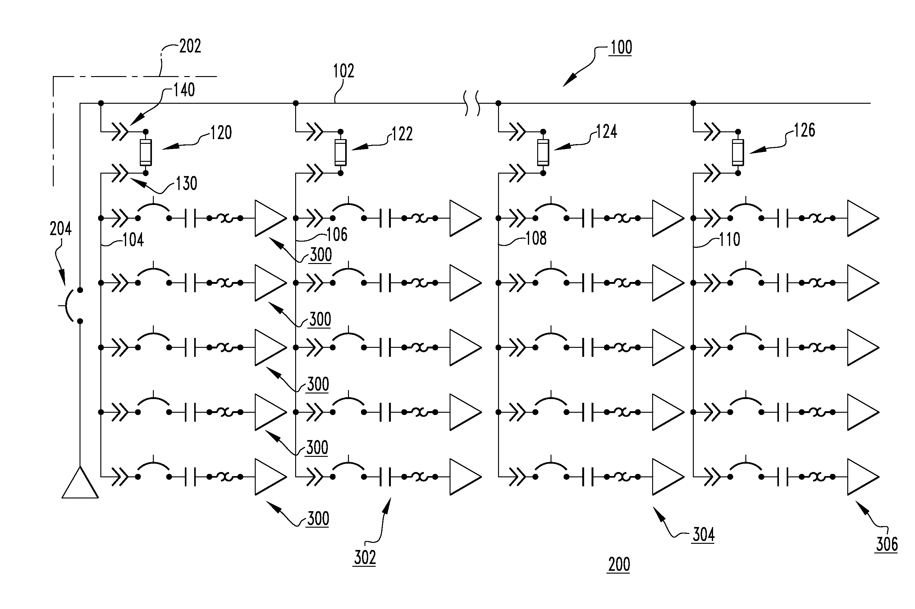
[0021]As employed herein, the term “low voltage control gear” refers to any known or suitable electrical apparatus having a horizontal bus feeding a series of vertical buses and associated electrical switching apparatus or subunits and expressly includes, but is not limited to, motor control centers and switchboards.
[0022]As employed herein, the statement that two or more parts are “connected” or “coupled” together shall mean that the parts are joined together either directly or joined through one or more intermediate parts. Further, as employed herein, the statement that two or more parts are “attached” shall mean that the parts are joined together directly.
[0023]As employed herein, the term “number” shall mean one or an integer greater than one (i.e., a plurality).
[0024]FIGS. 4 and 5 show schematic diagrams of a bu...
PUM
 Abstract
Description
Claims
Application Information