Multiplexer method and system for intrinsically safe applications and a multiplexer switch for use therein

Active Publication Date: 2005-02-24
SIMMONDS PRECISION PRODS
View PDF5 Cites 7 Cited by
  • Summary
  • Abstract
  • Description
  • Claims
  • Application Information

AI Technical Summary

Benefits of technology

[0010] In accordance with one aspect of the present invention, a multiplexer switch comprises: at least one field effect transistor having a current channel connected in series with a signal line that penetrates a tank containing a potentially explosive environment; an isolation circuit; and a drive circuit coupled to the at least one field effect transistor through

Problems solved by technology

Having dedicated intrinsically safe excitation and signal conditioning circuits for each sensor of the contained environment is very expensive and complex.
Thus, if a failure occurs within the switch, this drive voltage may become directly connected to the corresponding signal line, resulting in a defeat of the intrinsically safe design.
Conventional multiplexer switches have significant “on” resistance such that the current drawn by the signal line capacitance cause an undesirable voltage drop across the switch, resulting in a measurement error which may be in the range of five percent or so.
Further, reactive loading of the excitation signal can often cause an amplifier driving the signal to become unstable.
However, the addition of significant switch resistance in series with the excitation signal may interfere with the sensitive stability design of the drive amplifier.
The current of the response signal which flows through this switch “on” resistance results in a voltage drop across the stray line capacitance, that, in turn, diverts some of the sensor response current to ground through the line capacitance.
This undesirable diversion of current may also result in a measurement error.

Method used


Image

  • Multiplexer method and system for intrinsically safe applications and a multiplexer switch for use therein
  • Multiplexer method and system for intrinsically safe applications and a multiplexer switch for use therein
  • Multiplexer method and system for intrinsically safe applications and a multiplexer switch for use therein

Examples


Embodiment Construction

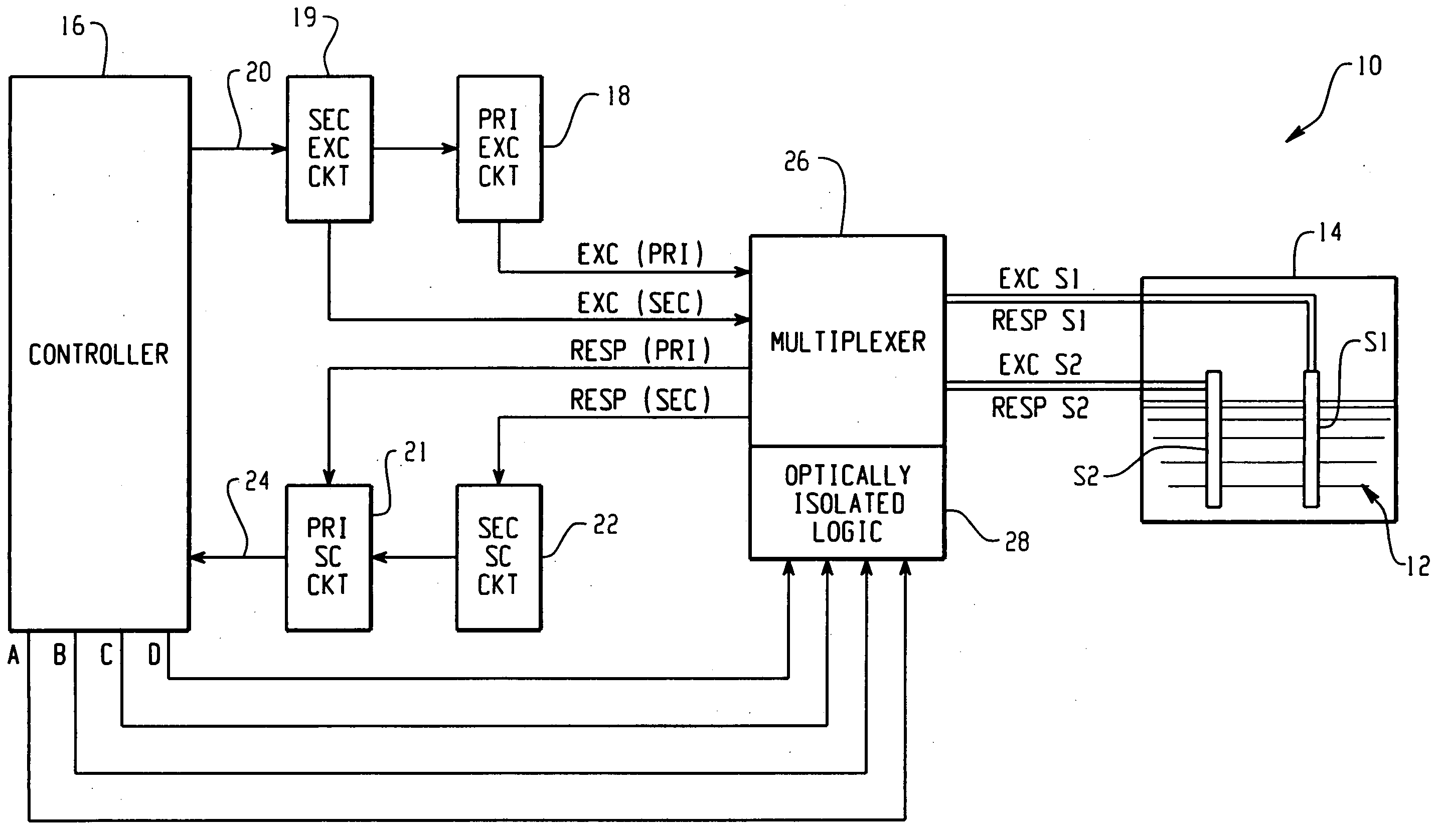
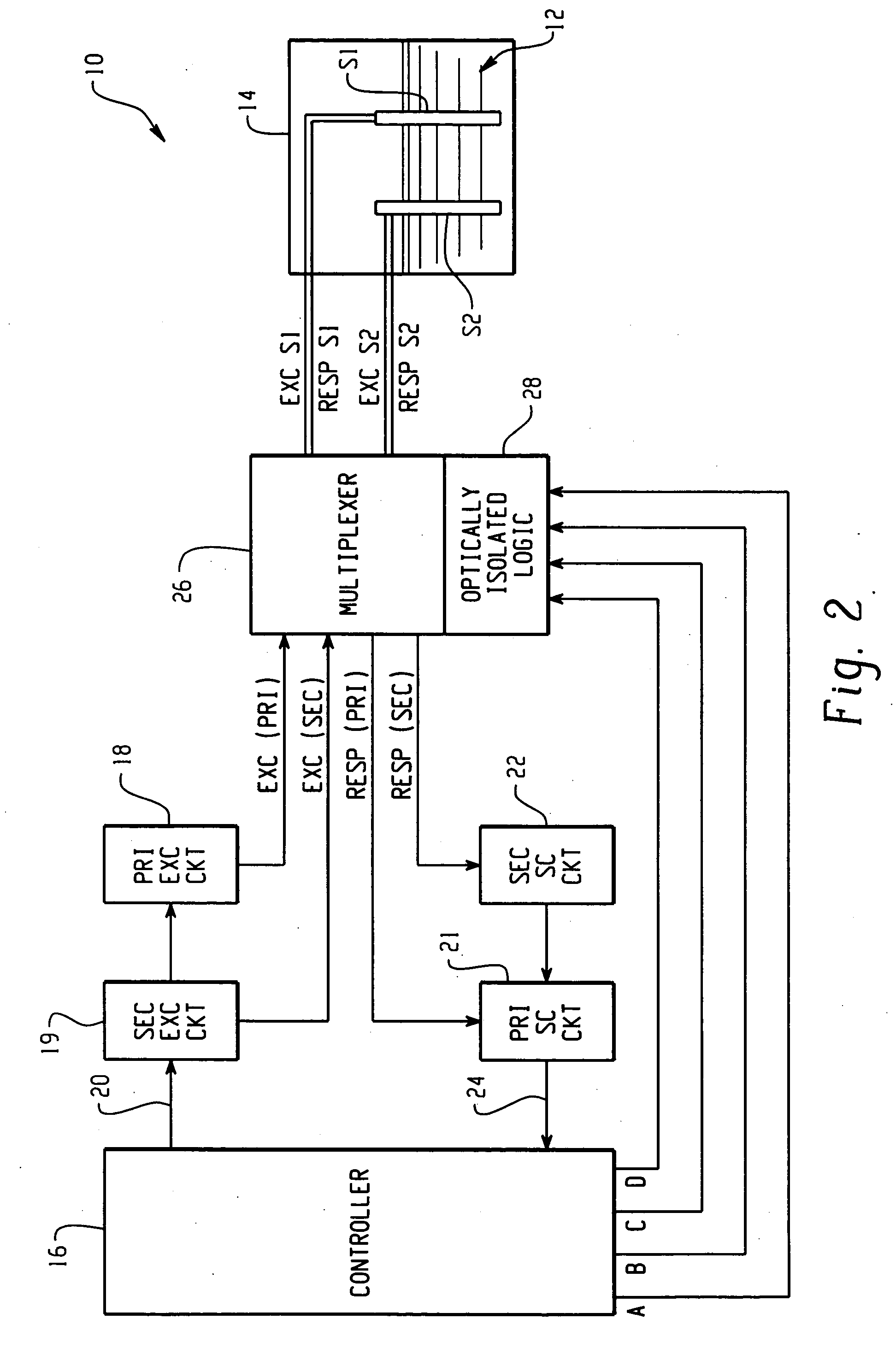
[0017] One aspect of the present invention is directed to a multiplexing system and a multiplexer switch for use therein that permits a plurality of sensors to be successively excited and read by a single electronics channel or the entire plurality excited and read by two or more electronic channels. The multiplexer switching function of the present invention can be performed directly in the signal lines of sensor leads even with impedance sensitive sensor signaling, and with circuits that have been stabilized for reactive loads without upsetting the circuit stability. In addition, it can be applied to circuits where it is critical that the sensor signal exactly match a reference signal. More particularly, all of the switching functions of the multiplexer system can be accomplished in circuits or signal lines that have been designed for intrinsically safe applications without compromising the intrinsically safe nature of the circuitry or signal lines.

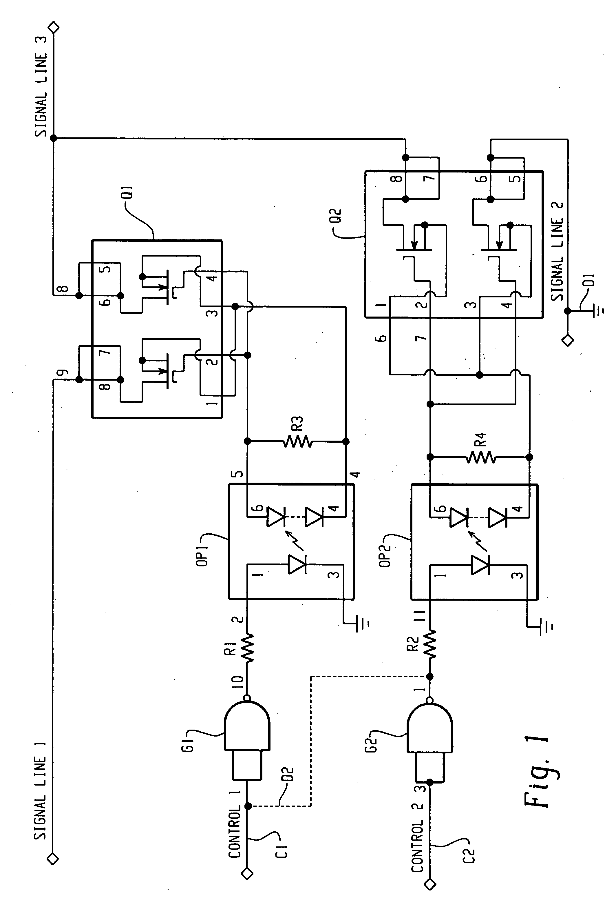
[0018]FIG. 1 is a circuit schem...


PUM


Abstract

A multiplexing system is provided for a plurality of sensors disposed in a tank containing a potentially explosive environment and excited from a common excitation circuit outside of the tank through a corresponding plurality of signal lines that penetrate the tank. The multiplexing system comprises: a multiplexer switch for each sensor, each multiplexer switch disposed outside of the tank in series with the corresponding signal line between the common excitation circuit and the corresponding sensor in the tank. Each multiplexer switch comprises: at least one field effect transistor having a current channel connected in series with the corresponding signal line; an isolation circuit; and a drive circuit coupled to the at least one field effect transistor through the isolation circuit for operating the current channel thereof, the isolation circuit electrically isolating the drive circuit from the at least one field effect transistor to limit energy coupled to the corresponding signal line through the at least one field effect transistor to below levels that could initiate an ignition of the potentially explosive environment of the tank. A multiplexing method is also disclosed.

Description

[0001] This application claims the benefit of the filing date Aug. 7, 2003 of the U. S. Provisional Patent Application No. 60 / 493,262.BACKGROUND OF THE INVENTION [0002] The present invention relates to intrinsically safe circuits and systems, in general, and more particularly to a multiplexing method and system for a plurality of sensors disposed in a tank containing a potentially explosive environment, and a multiplexer switch for use therein. [0003] In systems which supply signals to and receive signals from a contained environment comprising combustible or explosive vapors, restrictions are imposed to limit the energy over the signal lines penetrating the container below levels that could initiate an ignition of such vapors. For example, in a fuel quantity measurement system, sensors are disposed within a fuel tank and when excited, provide response signals indicative of the fuel level in the tank. Accordingly, each sensor has an excitation signal line and response signal line th...

Claims


Application Information

Patent Timeline
IPC IPC(8): G06F15/00H03K17/687H03K17/693H03K17/785
CPCH03K17/6874H03K17/785H03K17/693
Inventor MAIER, LAWRENCE CARL
Owner SIMMONDS PRECISION PRODS
Why Eureka
Try Eureka