System and Method of Using Location Technology to Aid Patient Recovery

Active Publication Date: 2012-02-09
GENERAL ELECTRIC CO
View PDF23 Cites 27 Cited by
  • Summary
  • Abstract
  • Description
  • Claims
  • Application Information

AI Technical Summary

Problems solved by technology

In some settings, a patient may be provided with a pedometer that measures distance traveled by the patient over the course of a da

Method used


Image

  • System and Method of Using Location Technology to Aid Patient Recovery
  • System and Method of Using Location Technology to Aid Patient Recovery
  • System and Method of Using Location Technology to Aid Patient Recovery

Examples


Embodiment Construction

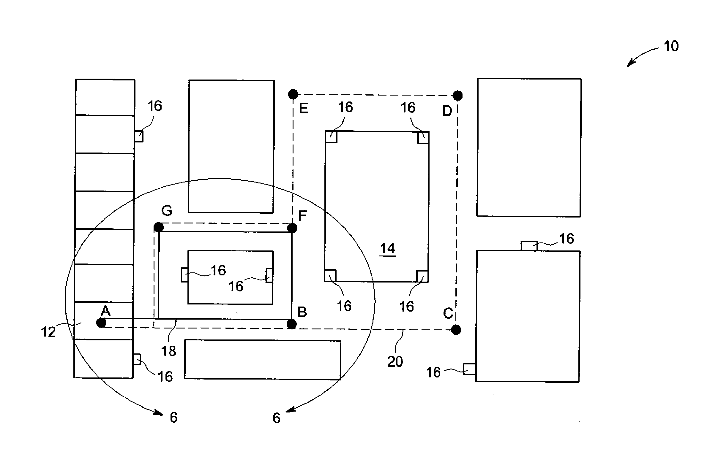
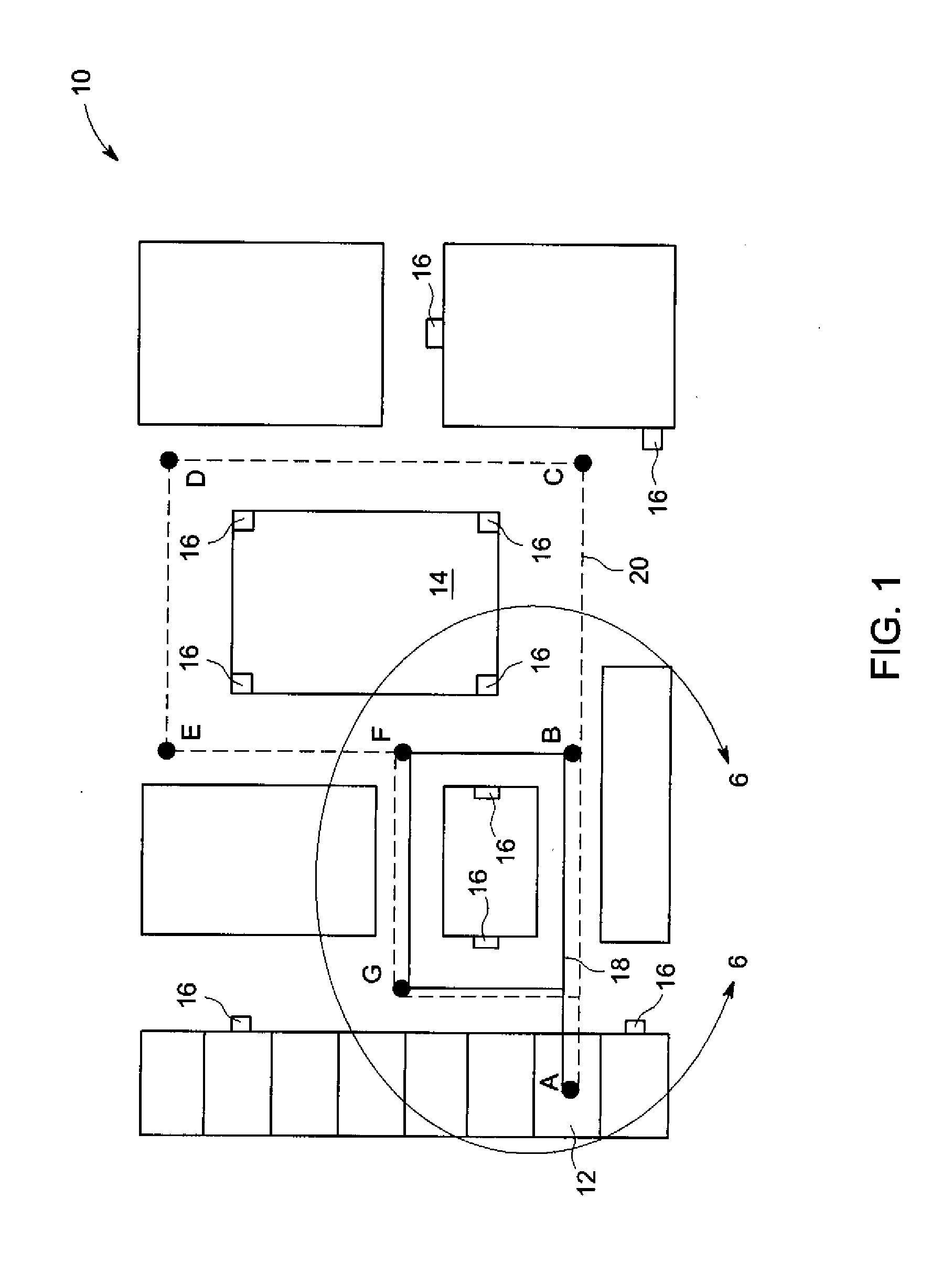
[0013]FIG. 1 depicts a floor plan 10 of a telemetry ward or other clinical setting. The floor plan 10 includes a variety of exemplary landmarks on the floor. These landmarks include a patient's room 12 and a nursing station 14. Additionally, the floor plan 10 exemplarily includes a plurality of telemetry receivers 16 disposed throughout the floor plan 10. Embodiments of the systems and methods incorporating one or more of these telemetry receivers 16 will be described in further detail herein. It is to be understood that alternative embodiments do not include a plurality of telemetry receivers 16, as will also be explained in further detail herein.

[0014]The floor plan 10 further includes two alternative routes 18, 20 for an ambulatory patient to travel. A short route 18 is represented by a solid line that connects the path A-B-F-G. A long route 20 is represented by a dashed line and follows the path represented by A-B-C-D-E-F-G.

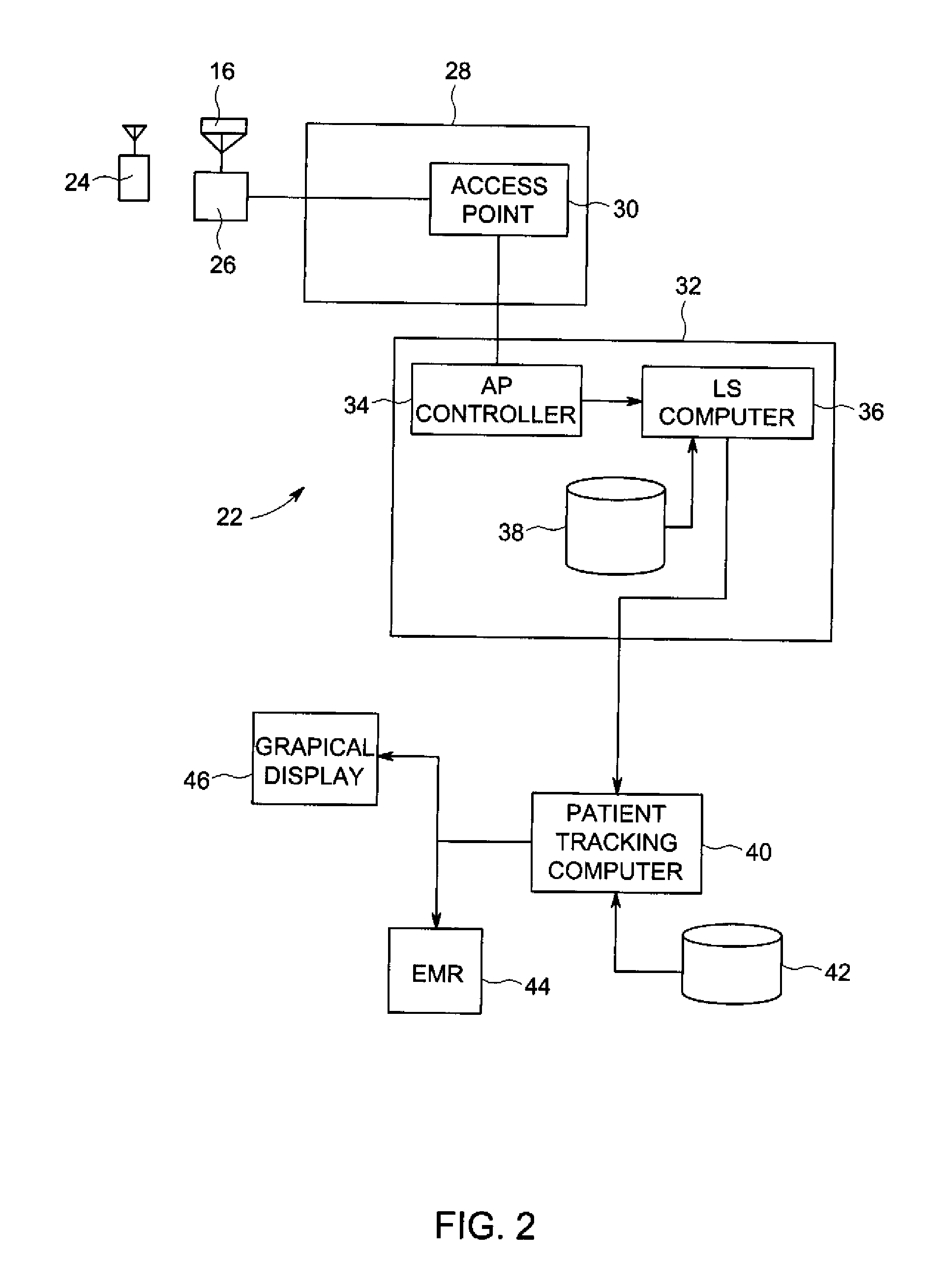
[0015]FIG. 2 is a schematic diagram of one possible arr...


PUM


Abstract

A system for telemetrically monitoring a patient includes a remote monitoring device associated with the patient. A location services system tracks a location of the remote monitoring device. A patient tracking computer calculates a distance and a duration of patient ambulation from the tracked location. A method of monitoring an ambulatory patient monitors the location of a remote monitoring device and derives ambulatory event data from the monitored location.

Description

BACKGROUND[0001]The present disclosure is related to the field of telemetry. More particularly, the present disclosure is related to systems and methods of monitoring patient location in order to aid in patient recovery.[0002]Patients recovering in telemetry wards or other hospital settings are often encouraged to exercise, if possible, by walking. Currently, this is merely encouraged or requested of the patient, but no specific demands are made.[0003]In some settings, a patient may be provided with a pedometer that measures distance traveled by the patient over the course of a day, but this information must be manually recorded by a clinician and there is no ability to differentiate types of patient movement.BRIEF DISCLOSURE[0004]A system for telemetrically monitoring a patient includes a remote monitoring device associated with the patient. The remote monitoring device obtains a physiological value from the patient and broadcasts the physiological value. A location services (LS) s...

Claims


Application Information

Patent Timeline
IPC IPC(8): A61B5/00
CPCG06F19/3418G16H50/20G07C9/00111G06F19/34G01S19/01A61B5/112A61B5/0002G07C1/10G16H40/20A61B5/113A61B2505/09A61B5/742A61B5/72G01S2013/468G01S17/08A61B5/1112G07C9/28G16H40/67G16H10/60
Inventor FRIEDMAN, BRUCE A.GRUBIS, MATTHEWNANTZ, BRIAN W.DAVIS, CARL C.
Owner GENERAL ELECTRIC CO
Why Eureka
Try Eureka