System for optimizing and controlling particle size distribution and production of nanoparticles in furnace reactor

a technology of nanoparticles and furnace reactors, which is applied in the direction of liquid-gas reaction processes, machines/engines, process and machine control, etc., can solve the problems of not determining failing to disclose a method to configure the stream of reactors without experimentation, and unable to determine the influence of process parameters on particle size distribution. , to achieve the effect of less experimentation, less time, and controlled properties cos

Inactive Publication Date: 2012-02-09
TATA CONSULTANCY SERVICES LTD
View PDF0 Cites 6 Cited by
  • Summary
  • Abstract
  • Description
  • Claims
  • Application Information

AI Technical Summary

Benefits of technology

[0030]The present invention provides a simulation tool for production of nanoparticles with controlled properties cost effectively requiring less experimentation and utilizing less time.

Problems solved by technology

Though the process for production of fine particles is well established, the challenging task is to control the product particle size and particle size distribution in furnace reactors for large scale production.
Though the '435 patent application discloses a method and apparatus for production of nanoparticles, it fails to disclose a method to configure the streams of the reactor without experimentation.
Further, it does not determine the influence of process parameters on particle size distribution.
Though the '596 patent application discloses a method and apparatus for the controlled synthesis of nanoparticles, it fails to disclose a method to configure the streams of the reactor without experimentation.
Further, it does not determine the influence of process parameters on particle size distribution.
This work was focused mainly on the size distribution of particles only and did not address the coupling of the gas phase dynamics with particle population dynamics.
Further, the said article does not determine the gas phase and particle characteristics throughout the furnace reactor and the particle characteristics using various burners.
It also does not address the challenging aspects for the scale-up of production of nanoparticles with the desired particle size distribution.

Method used


Image

  • System for optimizing and controlling particle size distribution and production of nanoparticles in furnace reactor
  • System for optimizing and controlling particle size distribution and production of nanoparticles in furnace reactor
  • System for optimizing and controlling particle size distribution and production of nanoparticles in furnace reactor

Examples


example 1

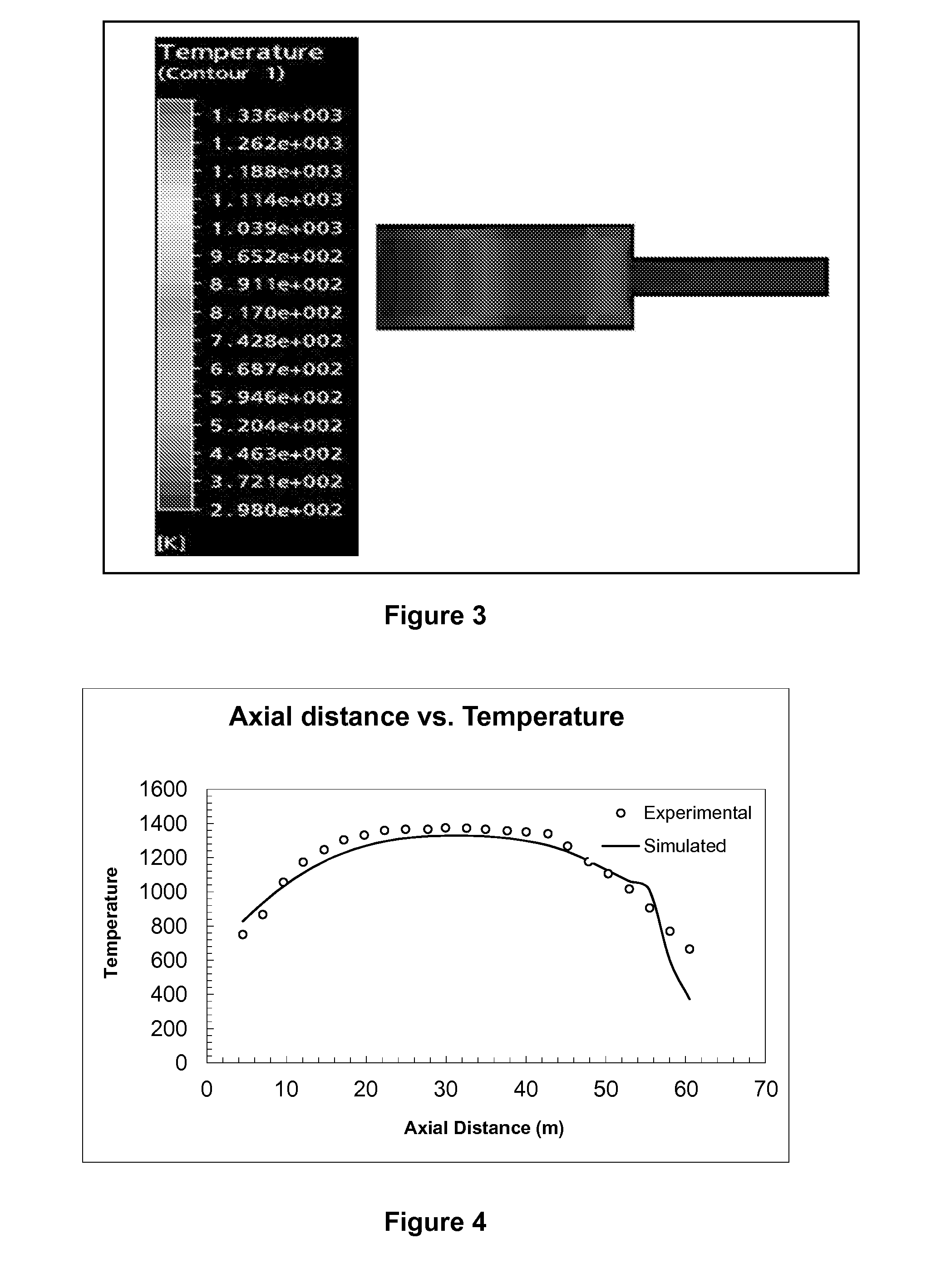
[0109]FIG. 4 illustrates the comparison of axial temperature profile in a furnace reactor determined by simulation tool of the present invention with experimental data of Akhtar et al (1991), at a set furnace temperature of 1400 K.

[0110]According to one of the exemplary embodiments of the present invention, the simulation tool of the present invention was tested to compare axial temperature profile in a furnace reactor. The temperature profile determined by the simulation tool of the present invention is compared to the temperature profile obtained experimentally. The experimental data of Akhtar et al (1991) was used to compare the temperature profile determined by the simulation tool of present invention.

[0111]Further, Table 1 below provides and compares the simulated data determined by the simulation tool with programmed instructions for the axial temperature profile in a furnace reactor with that of published experimental data of Akhtar et al (1991).

[0112]It can be observed from ...

example 2

[0113]FIG. 5 illustrates the comparison of titanium dioxide particle size distribution curves obtained using a precursor (TiCl4) concentration of 1.16×10⁻⁵ mol / l in at a furnace temperature of 1723 K determined by simulation tool of the present invention with experimental data of Akhtar et al (1991).

[0114]According to one of the exemplary embodiments of the present invention, the simulation tool of the present invention was tested for determination of titanium dioxide particle size distribution curves for TiCl4 concentration of 1.16×10⁻⁵ mol / l at a set furnace temperature of 1723 K.

[0115]Further, Table 2(a) and 2(b) below provide and compare the simulated data determined by the simulation tool with programmed instructions with that of published experimental data of Akhtar et al (1991) simultaneously for titanium dioxide particle size distribution curves for TiCl4 concentration of 1.16×10⁻⁵ mol / l in at a furnace temperature of 1723 K.

TABLE 2(a)NormalizedParticleParticle NumberSize (μ...

example 3

[0117]FIG. 6 illustrates the comparison of titanium particle size distribution curves for TiCl4 concentration of 1.56×10⁻⁵ mol / l at a furnace temperature of 1400 K determined by simulation tool of the present invention with the experimental data of Akhtar et al (1991).

[0118]According to one of the exemplary embodiments of the present invention, the simulation tool of the present invention was tested further for prediction of titanium particle size distribution curves for TiCl4 concentration of 1.56×10⁻⁵ mol / l in a furnace temperature of 1400 K.

[0119]Further, Table 3(a) and 3(b) below provide and compare the simulated data determined by the simulation tool with programmed instructions with that of published experimental data of Akhtar et al (1991) simultaneously for titanium dioxide particle size distribution curves for TiCl4 concentration of 1.56×10⁻⁵ mol / l in at a furnace temperature of 1400 K.

TABLE 3(a)NormalizedParticleParticle NumberSize (μm)Concentration0.1280.01040.13270.02050...


PUM

PropertyMeasurementUnit
diameteraaaaaaaaaa
diameteraaaaaaaaaa
sizeaaaaaaaaaa

Abstract

The present invention relates to a system for optimizing and controlling the particle size distribution and production of nanoparticles in a furnace reactor. The method provides nanoparticles with desired, optimized and controlled particle size distribution and specific surface area in furnace reactors using a simulation tool with programmed instructions. The said simulation tool couples flame dynamics module and particle population balance module and precursor reaction kinetics module.

Description

CROSS REFERENCE TO RELATED APPLICATION[S][0001]This application claims priority to Indian Patent Application to Runkana, et al., serial number 2246 / MUM / 2010, filed Aug. 9, 2010, the disclosure of which is hereby incorporated entirely herein by reference.FIELD OF THE INVENTION[0002]The present invention relates to a system for optimizing particle size distribution and production of nanoparticles in furnace reactors. More particularly the present invention relates to a system and method for production of nanoparticles with desired particle characteristics.BACKGROUND OF THE INVENTION AND PRIOR ART[0003]In the recent years, nanotechnology has gained importance and has become one of the research focus areas for its fundamental and practical applications. Fine particles are usually produced in furnace reactors on the industrial scale with annual production of several metric tons per hour. The smaller size of the particles especially less than 100 nm is one of the key parameters that is re...

Claims


Application Information

Patent Timeline
Patent Type & Authority Applications(United States)
IPC IPC(8): B01J19/00G05B13/04
CPCB82Y30/00C01G1/02C01G23/07C01P2004/64C01P2006/12C04B35/62665C04B2235/3232C04B2235/5445C04B2235/5481
Inventor RUNKANA, VENKATARAMANABUDDHIRAJU, VENKATA SUDHEENDRA
Owner TATA CONSULTANCY SERVICES LTD
Why Eureka
Try Eureka