System for optimizing and controlling particle size distribution and for scale-up of nanoparticle production in an aerosol flame reactor

a technology of aerosol flame reactor and particle size distribution, which is applied in the field of system and method for optimizing and controlling the particle size distribution and the scale-up of nanoparticle production in aerosol flame reactor, can solve the problems of not addressing the challenge aspect of 446 patent, irregular structure of particles and particle distribution, and inability to disclose the optimization method, etc., to achieve less experimentation, less time, and less experimentation

Active Publication Date: 2014-08-12
TATA CONSULTANCY SERVICES LTD
View PDF2 Cites 0 Cited by
  • Summary
  • Abstract
  • Description
  • Claims
  • Application Information

AI Technical Summary

Benefits of technology

[0033]Another object of the invention is to provide system and method which optimizes and controls the particle size and specific surface area of nanoparticles in an aerosol flame reactor requiring less experimentation and utilizing less time.
[0034]Another object of the invention is to provide a method for scaling up synthesis of nanoparticles in an aerosol flame reactor which requires less experimentation.

Problems solved by technology

The temperature decrease at the downstream of the reactor results in the particle growth mainly by coagulation and results in irregularly structured particles and particle distribution.
Yet another challenging task lies in scaling up of the process to produce nanoparticles in large quantities, while at the same time maintaining the particle size in the nanometer range.
Though the '446 patent discloses a method and apparatus for synthesis of nanoparticles, it does not disclose the means for optimization, and controlled particle size distribution of nanoparticles.
Further, '446 patent does not address challenging aspect for the scale-up of production of nanoparticles with the desired particle size.
Hence, the patent application discloses a method to control particle characteristics of flame made nanostructured powders experimentally, which is expensive and time consuming.
Further, the article does not determine the particle characteristics throughout the reactor and does not determine the particle characteristics using various burners and does not address the challenging aspect for the scale-up of production of nanoparticles with the desired particle size.
Further, the simple kinetics used in the article only applies for a limited range of temperature and particle size.
It is also evident that the process equipment design and scale-up, pilot scale studies are tedious and expensive.

Method used


Image

  • System for optimizing and controlling particle size distribution and for scale-up of nanoparticle production in an aerosol flame reactor
  • System for optimizing and controlling particle size distribution and for scale-up of nanoparticle production in an aerosol flame reactor
  • System for optimizing and controlling particle size distribution and for scale-up of nanoparticle production in an aerosol flame reactor

Examples


example 1

[0128]FIG. 4 shows the temperature contours and the value of the alumina aggregate particle size inside the flame reactor with burner configuration B (Flame B) of FIG. 3, wherein methane in the input stream is fed to the burner through the third tube; air in the second tube and precursor and carrier gas in the first tube.

[0129]The configuration of input streams (methane, air, carrier gas and precursor) to the burner has a strong influence on the flame characteristics and hence on the particle size. The influence of burner configuration and arrangement of the burner configurations on flame temperature profile is shown in FIG. 4.

[0130]The flames in configuration B (FIG. 4) are shorter flames surrounded by air on both sides and hence, yield a more efficient combustion.

example 2

[0131]FIG. 5 shows the temperature contours and the value of the alumina aggregate particle size inside the flame reactor with burner configuration C (Flame C) of FIG. 3, wherein methane in the input stream is fed to the burner through the second tube; air in the third tube and precursor and carrier gas in the first tube.

[0132]The configuration of input streams to the burner has a strong influence on the flame characteristics and hence on the particle size. The influence of burner configuration on flame temperature profile is shown in FIG. 5.

[0133]The configuration B (flame B) has methane in the third tube and air in the second tube where as configuration C has methane in the second tube and air in the third tube. This difference in arrangement alters the flame shape and size drastically as seen in the FIGS. 4 and 5.

[0134]The flames in configuration B (FIG. 4) are surrounded by air on both sides and hence, yield a more efficient combustion than those in configuration C.

[0135]For thi...

example 3

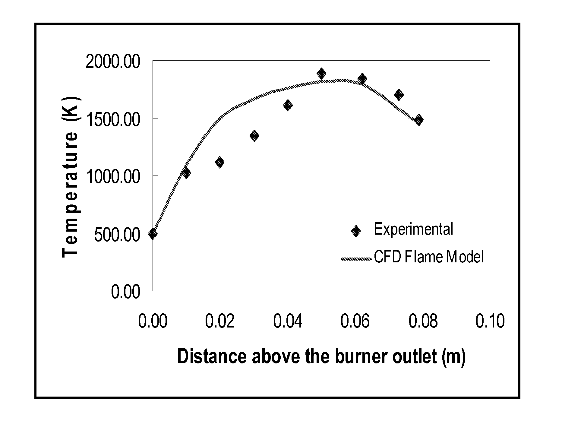
[0136]FIG. 6 illustrates the comparison of axial temperature profile in a laboratory scale flame reactor determined by simulation tool of the present invention with the experimental data of Johanessen et al (T. Johannessen, S. E. Pratsinis and H. Livbjerg, Computational fluid-particle dynamics for the flame synthesis of alumina particles, Chemical Engineering Science, 55, 177-191 (2000)).

[0137]FIG. 6 compares the data determined by the simulation tool with programmed instructions for the axial temperature profile and influence of distance above burner outlet (m) on the mean particle size with that of published experimental data of Johanessen et al (2000).

[0138]Further, Table 1 below provides and compares the simulated data determined by the simulation tool with programmed instructions for the axial temperature profile and influence of distance above burner outlet (m) on the mean particle size with that of published experimental data of Johanessen et al (2000).

[0139]

TABLE 1Distance a...


PUM

PropertyMeasurementUnit
sizeaaaaaaaaaa
inner diameteraaaaaaaaaa

Abstract

The present invention relates to a system for optimizing and controlling the particle size distribution and scale-up of production of nanoparticle in an aerosol flame reactor. The method provides nanoparticles with desired, optimized and controlled particle size and the specific surface area in aerosol reactors using a simulation tool with programmed instructions. The simulation tool couples flame dynamics model and particle population balance model.

Description

CROSS REFERENCE TO RELATED APPLICATION[S][0001]This application claims priority to Indian Patent Application to Runkana, et al., serial number 1984 / MUM / 2010, filed Jul. 12, 2010, the disclosure of which is hereby incorporated entirely herein by reference.FIELD OF INVENTION[0002]The present invention relates to a system and a method for optimizing and controlling the particle size distribution and for scale-up of production of nanoparticles in an aerosol flame reactor. More particularly the present invention relates to a system and a method for optimization of mean particle size, specific surface area, and distribution of nanoparticles in aerosol reactors.BACKGROUND OF THE INVENTION AND PRIOR ART[0003]In the recent years, nanotechnology has gained importance and has become one of the major research focus areas for its fundamental and practical applications. The smaller size of the particles especially less than 100 nm is one of the key parameters that is responsible for various prope...

Claims


Application Information

Patent Timeline
Patent Type & Authority Patents(United States)
IPC IPC(8): C01F7/02
CPCY10T436/115831C01B33/18C01P2004/62C01P2004/51C01B13/20Y10T436/12B82Y30/00C01P2004/61C01G23/047B01J19/0033C01P2006/12C01P2004/52C01P2004/64C01G23/07
Inventor RUNKANA, VENKATARAMANABUDDHIRAJU, VENKATA SUDHEENDRAVARMA NADIMPALLI, NAGARAVI KUMAR
Owner TATA CONSULTANCY SERVICES LTD
Why Eureka
Try Eureka