Closed Cycle Brayton Cycle System and Method

a closed-cycle technology, applied in the direction of machines/engines, mechanical equipment, liquid fuel engines, etc., can solve the problem that the existing closed-cycle brayton cycle system is not very efficien

Inactive Publication Date: 2012-02-16
NUOVO PIGNONE SPA
View PDF9 Cites 56 Cited by
  • Summary
  • Abstract
  • Description
  • Claims
  • Application Information

AI Technical Summary

Problems solved by technology

However, the existing closed Brayton cycle systems are not very efficient.

Method used


Image

  • Closed Cycle Brayton Cycle System and Method
  • Closed Cycle Brayton Cycle System and Method
  • Closed Cycle Brayton Cycle System and Method

Examples


Embodiment Construction

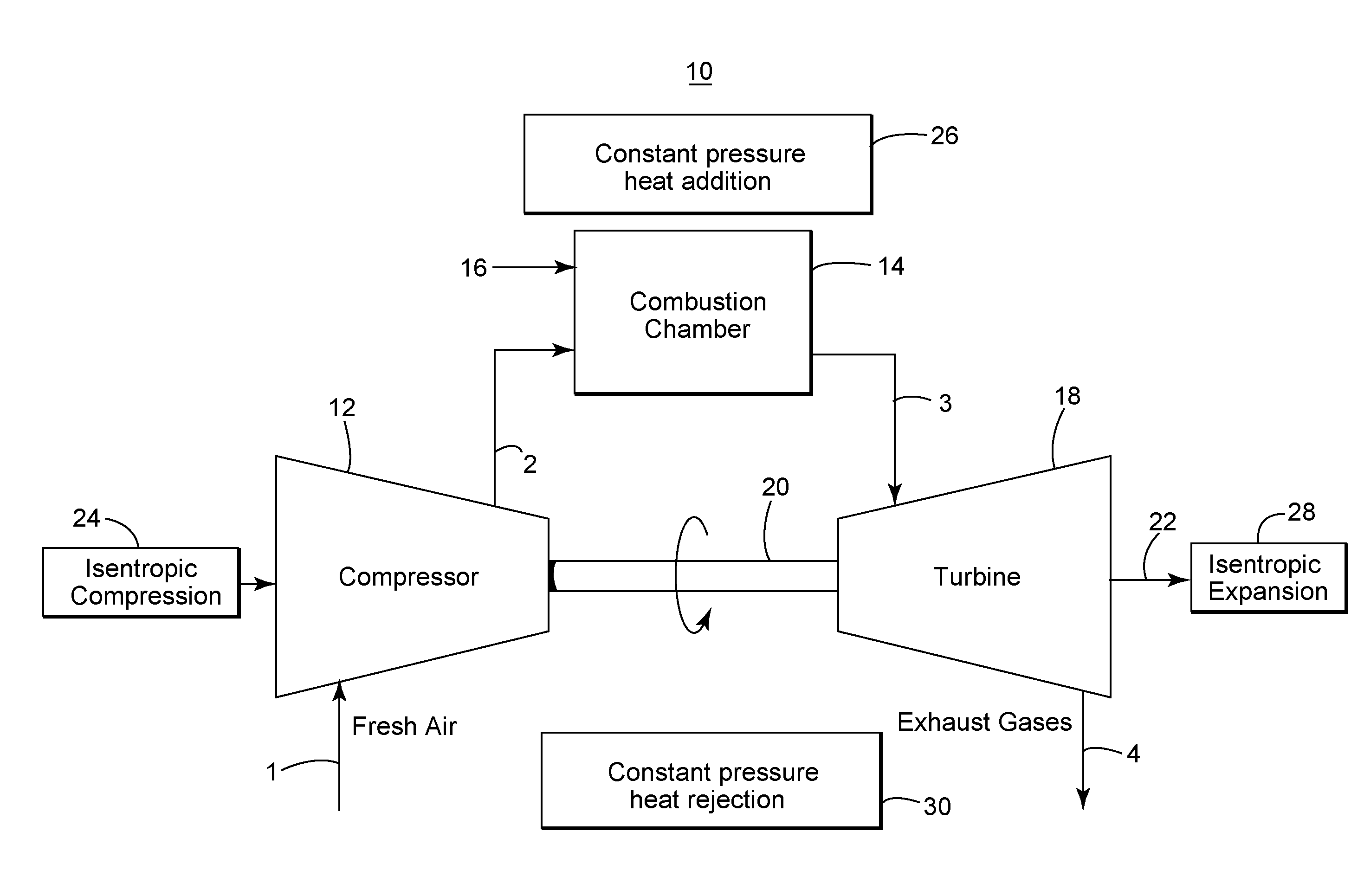
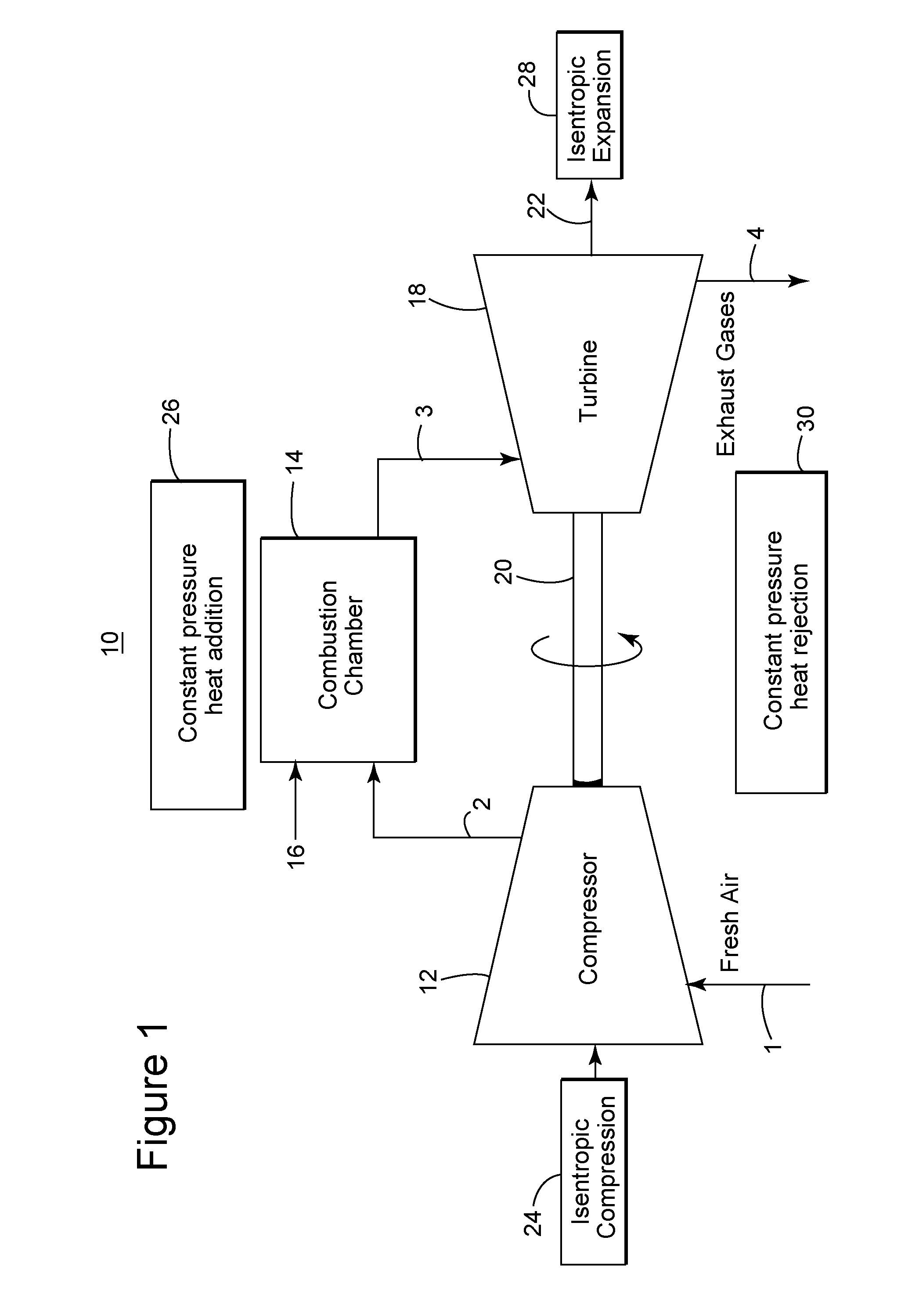
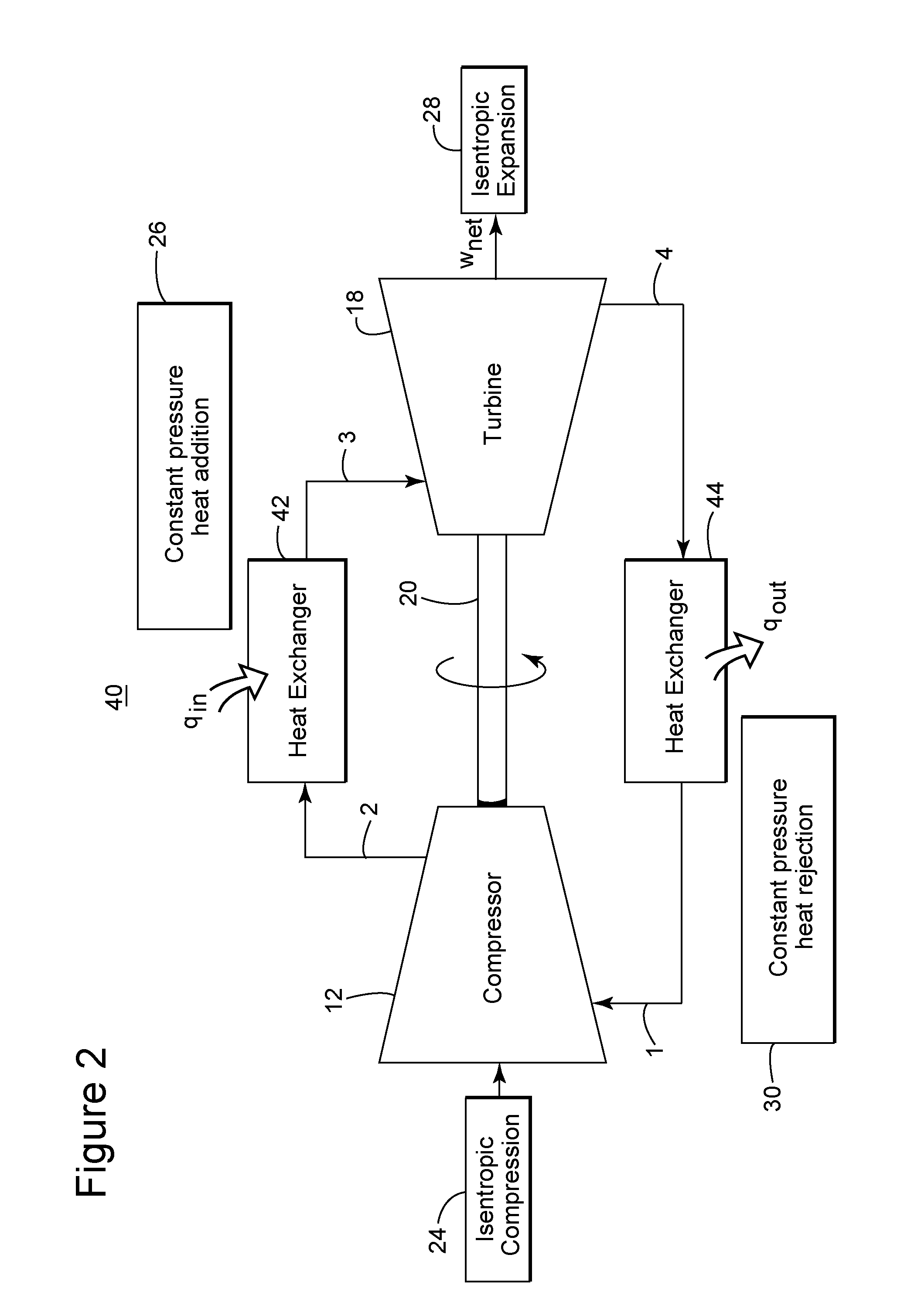
[0019]The following description of the exemplary embodiments refers to the accompanying drawings. The same reference numbers in different drawings identify the same or similar elements. The following detailed description does not limit the invention. Instead, the scope of the invention is defined by the appended claims. The following embodiments are discussed, for simplicity, with regard to the terminology and structure of a system having an integrally geared compressor (technology to be discussed later) and a multiple stage radial or axial expander. However, the embodiments to be discussed next are not limited to these systems, but may be applied to other systems that use multistage compressors and expanders in a closed cycle.

[0020]Reference throughout the specification to “one embodiment” or “an embodiment” means that a particular feature, structure, or characteristic described in connection with an embodiment is included in at least one embodiment of the subject matter disclosed....


PUM


Abstract

Method and unit for generating energy with improved efficiency. A Brayton cycle unit includes a multistage compressor configured to compress a flowing medium; a first heat exchanger fluidly connected to the multistage compressor and configured to transfer heat from a working medium passing the first heat exchanger to the compressed flowing medium; an expander fluidly connected to the first heat exchanger and configured to expand the heated compressed flowing medium for producing a rotation of a shaft of the expander; and a second heat exchanger fluidly connected between the expander and the compressor and configured to remove heat from the expanded flowing medium. A path of the flowing medium through the unit is closed. At least one inter-cooler mechanism between first and second stages of the multistage compressor is configured to cool the flowing medium to a predetermined temperature.

Description

BACKGROUND[0001]1. Technical Field[0002]Embodiments of the subject matter disclosed herein generally relate to methods and systems and, more particularly, to mechanisms and techniques for increasing an efficiency of a closed cycle Brayton cycle system.[0003]2. Discussion of the Background[0004]During the past years, the use of gas turbines for providing thrust for most aircrafts, generating electricity, etc. has become popular. Gas turbines operate on a Brayton cycle and have a working fluid (usually air). The gas turbines may use an open or a closed Brayton cycle. FIG. 1 illustrates a system 10 that operates based on the open Brayton cycle. Fresh air is provided at a compressor 12 in step 1. After being compressed, the air is provided in step 2 to an internal combustor 14. At the same time, fuel 16 is injected and ignited into the combustion chamber 14 for heating the compressed air. After being heated, the high temperature, high pressure gases from the combustion chamber are provi...

Claims


Application Information

Patent Timeline
Patent Type & Authority Applications(United States)
IPC IPC(8): F04D27/02F04D29/58
CPCF02C1/10
Inventor DIDDI, PRADEEPKOSAMANA, BHASKARA
Owner NUOVO PIGNONE SPA
Why Eureka
Try Eureka