Saw blade

a technology of blades and blades, applied in the field of saw blades, can solve the problems of insufficiently secured blades for oscillating motion saws, serious bodily injury, and blade disengagement, and achieve the effect of enhancing the versatility of the saw and being convenient to moun

Inactive Publication Date: 2012-02-16
SMITH & NEPHEW INC
View PDF8 Cites 18 Cited by
  • Summary
  • Abstract
  • Description
  • Claims
  • Application Information

AI Technical Summary

Benefits of technology

[0009]Embodiments disclosed herein also include provision of a blade locking mechanism having a mounting arm and at least two locking pins provided in the cam. In use, the locking pins are retracted and the saw blade is inserted into a slot in the cam so that the mounting arm is received in the mounting cavity. The locking pins are then released and spring upwardly to engage one of the mounting slots, gradually biasing the mounting arm into the other of the mounting slots until the locking pins can fully extend into their respective positions within the mounting slot. The locking pins thereby retain the mounting arm in one of the mounting slots via their engagement with the other of the mounting slots and in this way prevent the blade from backing out of the cam.
[0010]The embodiments disclosed herein create and retain a rigid, secure connection between the saw blade and hub even after repeated and rapid oscillations of the saw blade during use. Moreover, the disclosed connection configuration renders it easy to mount and dismount the saw blade from the hub quickly without the need for tools, such as a wrench or key. Thus, embodiments disclosed herein eliminate the need to provide and sterilize such tools in the surgical suite and account for their presence after surgery. Rather, the embodiments disclosed herein make replacing saw blades, which often occurs during surgery, a relatively simple task and thus enhances the versatility of the saw.

Problems solved by technology

If the blade is not fully inserted and adequately secured within the hub, the repeated and rapid oscillations of the blade can lead to the disengagement of the blade during operation and thereby risk serious bodily injury.
Further, an inadequately secured blade for an oscillating motion saw generates a significant amount of noise.
This is because current saw blades do not tightly fit into the saw head slots.

Method used


Image

  • Saw blade
  • Saw blade
  • Saw blade

Examples


Embodiment Construction

[0031]The following description of the preferred embodiment(s) is merely exemplary in nature and is in no way intended to limit the invention, its application, or uses.

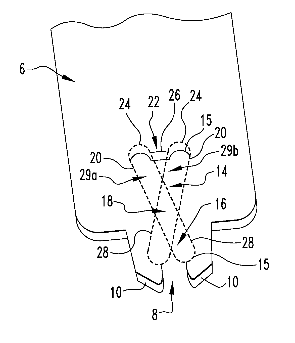
[0032]FIG. 4 illustrates one embodiment of a saw blade 6. The saw blade 6 may be formed from any material having suitable structural integrity and strength to cut bone. Suitable materials include, but are not limited to, metallic materials, such as stainless steel. One of skill in the art will readily understand that teeth 5 or other means for cutting bone would be provided on the saw blade. (See, e.g., FIGS. 18B, 24B, and 25B). Such teeth 5 could be provided along a distal end or side edge(s) of the saw blade 6. Teeth 5 may be arranged in a linear or in an arcuate fashion. The saw blade 6 also includes a mounting portion 9.

[0033]Teeth 5 need not be positioned along an outermost edge of saw blade 6, nor must saw blade 6 be planar. Rather, as illustrated in FIGS. 28-32, teeth 5 may be positioned at any location within ...


PUM

PropertyMeasurementUnit
angleaaaaaaaaaa
angleaaaaaaaaaa
angleaaaaaaaaaa

Abstract

There is provided a surgical saw blade for use in orthopaedic surgery. The saw blade comprising: a mounting cavity having a first substantially triangular-shaped opening and a second substantially triangular-shaped opening in communication with, and inverted relative to, the first opening, the first and second opening collectively define two mounting slots that form an angle relative to one another. In some embodiments, the planar portion further comprises an offset planar shelf. The offset shelf may be oriented along the length of the planar portion to allow for longitudinal reciprocation or may be oriented across the width of the planar portion to allow for lateral reciprocation.

Description

CROSS-REFERENCE TO RELATED APPLICATIONS[0001]This application claims the benefit of U.S. Provisional Application No. 61 / 373,522, filed Aug. 13, 2010 and U.S. Provisional Application No. 61 / 494,265, filed Jun. 7, 2011. The disclosure of this prior application is incorporated by reference in its entirety.BACKGROUND OF THE INVENTION[0002]1. Field of the Invention[0003]The present invention relates to saw hubs for use with powered surgical saws in orthopedic surgery and other operations involving cutting of bone.[0004]2. Related Art[0005]Powered saws are frequently used for surgical procedures including orthopedic surgery and other operations requiring cutting of bone. Such saws typically include a handpiece 2 by which the surgeon can support the saw 1, a hub 3 mounted on handpiece 2, and a saw blade 4 coupled to the hub 3, as seen generally in FIGS. 1-3. In use and upon activation by the surgeon, the hub moves to impart oscillatory motion to the saw blade rigidly attached to the hub. T...

Claims


Application Information

Patent Timeline
Patent Type & Authority Applications(United States)
IPC IPC(8): A61B17/16
CPCA61B17/148A61B17/141A61B17/142Y10T83/9377Y10T83/9457
Inventor LANDON, RYAN LLOYD
Owner SMITH & NEPHEW INC
Why Eureka
Try Eureka