Method and apparatus for printing on a substrate

a substrate and printing technology, applied in the direction of printing, coatings, inking apparatus, etc., can solve the problems of affecting etc., and achieving both the printability and the rigidity requirements of finished printed body often has difficulty in achieving both conditions well. , to achieve the effect of ensuring the quality of finished printed body

Inactive Publication Date: 2012-02-23
PRECO
View PDF10 Cites 30 Cited by
  • Summary
  • Abstract
  • Description
  • Claims
  • Application Information

AI Technical Summary

Problems solved by technology

That is, paste may change in its viscosity due to shearing or deforming that occurs in the process of printing.
In general, a paste designed for satisfying both the printability and the finished printed body rigidity requirements often has difficulty achieving both conditions well.
This means that these pastes, once printed, have difficulty keeping a crisp line definition, and are subject to slumping, thereby reducing the height of the trace while widening its base.
This condition adversely affects many production scenarios.
Conversely, a paste designed primarily for keeping a well-defined aspect ratio—the height of a printed line or trace in respect to its width—often does not fill stencil cavities well due to its resistance to shearing, and subsequently does not transfer consistently to a substrate.

Method used


Image

  • Method and apparatus for printing on a substrate
  • Method and apparatus for printing on a substrate
  • Method and apparatus for printing on a substrate

Examples


Embodiment Construction

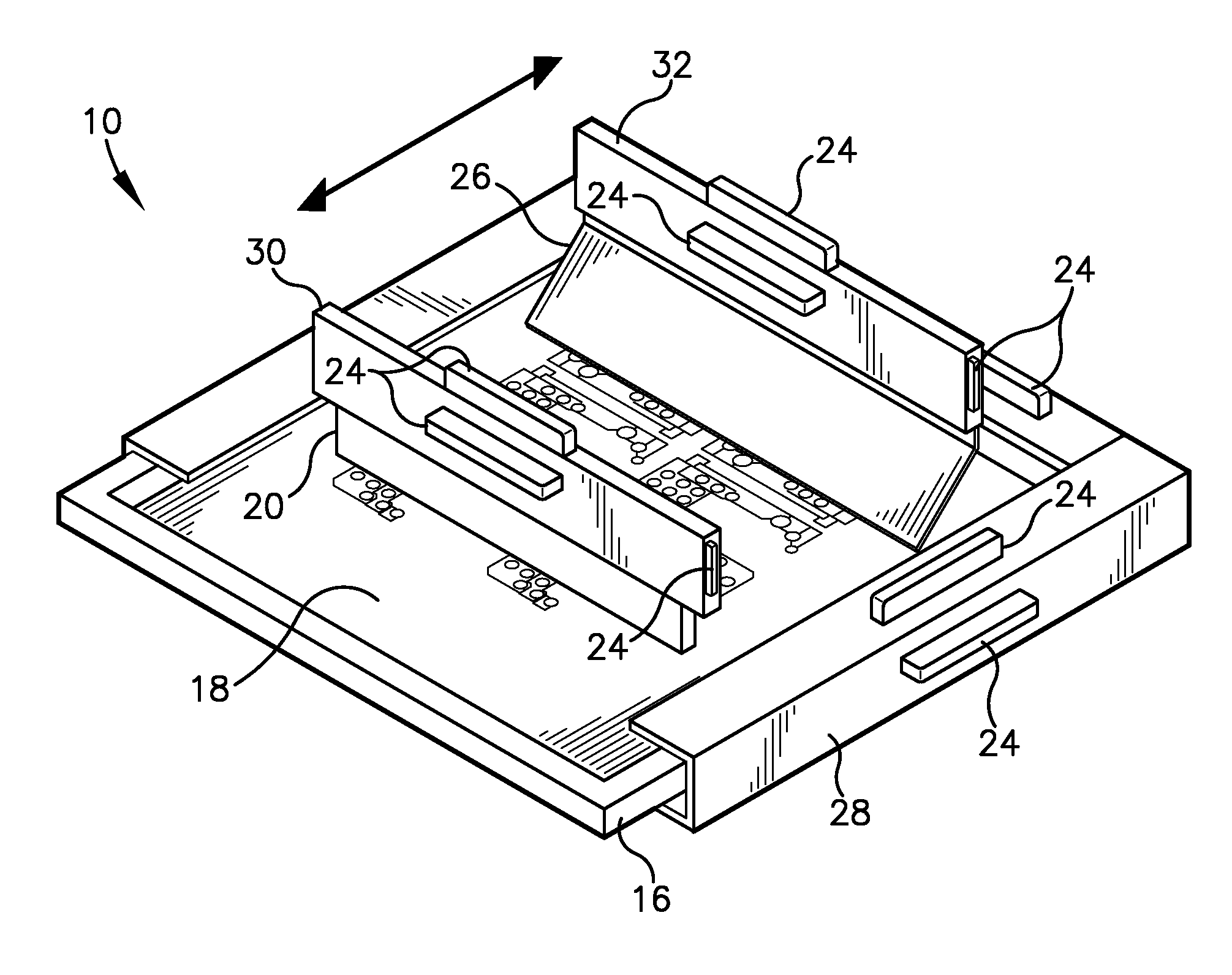
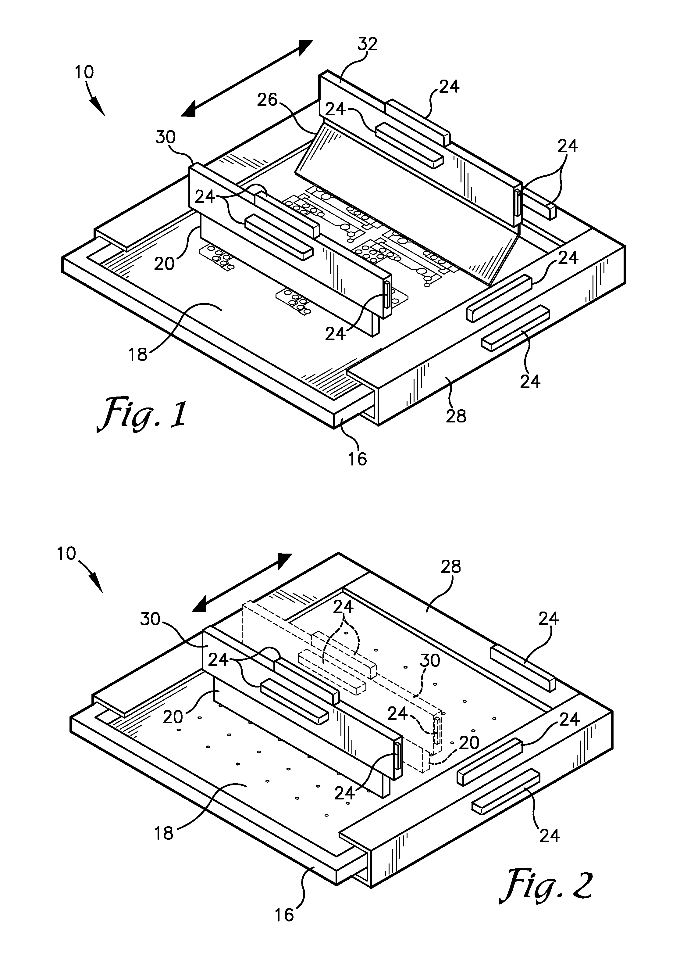
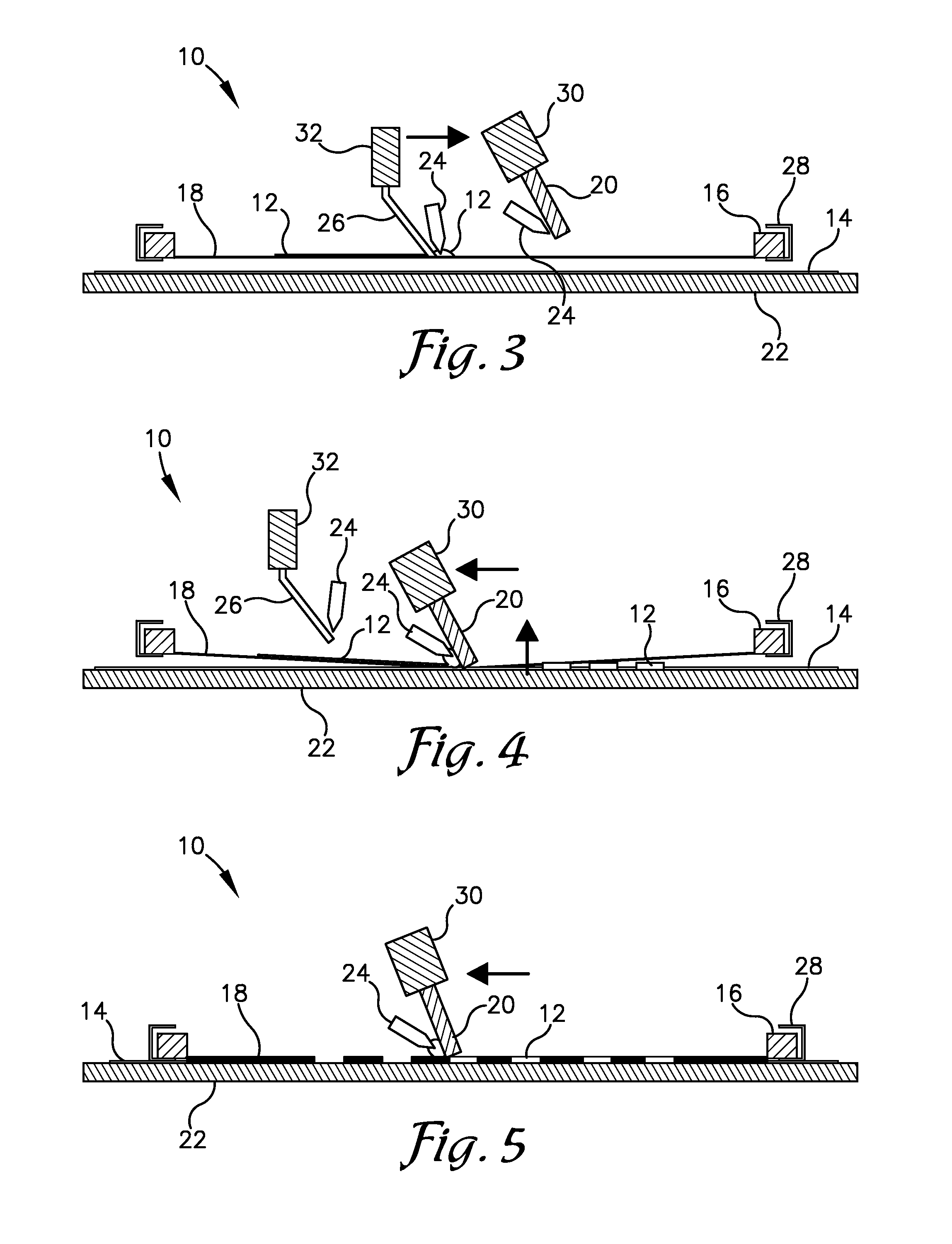
[0031]The following detailed description of the invention references the accompanying drawings that illustrate specific embodiments in which the invention can be practiced. The embodiments are intended to describe aspects of the invention in sufficient detail to enable those skilled in the art to practice the invention. Other embodiments can be utilized and changes can be made without departing from the scope of the present invention. The following detailed description is, therefore, not to be taken in a limiting sense. The scope of the present invention is defined only by the appended claims, along with the full scope of equivalents to which such claims are entitled.

[0032]In this description, references to “one embodiment”, “an embodiment”, or “embodiments” mean that the feature or features being referred to are included in at least one embodiment of the technology. Separate references to “one embodiment”, “an embodiment”, or “embodiments” in this description do not necessarily ref...


PUM


Abstract

A screen printing apparatus and method for applying paste to a substrate while agitating the paste through vibration or pulsating of one or more pulse sources. The screen printing apparatus may comprise a support structure including a frame, a stencil supported by the frame, a squeegee configured to contact the stencil and transfer the paste through apertures of the stencil, and at least one pulse source attached to the support structure and configured to agitate the paste on the stencil. The pulse sources may be configured to attach to and vibrate the frame, squeegee, or other components contacting the paste. Some of the pulse sources may vibrate in different directions relative to each other. In some embodiments of the invention, the pulse source may be configured to be directly inserted or immersed in the paste resting on the stencil during various steps of the printing method.

Description

RELATED APPLICATIONS[0001]This non-provisional patent application claims priority benefit to earlier-filed U.S. provisional patent application titled “Method and Apparatus for Enhancing the Attributes of a Printed Composition” Ser. No. 61 / 376,090, filed Aug. 23, 2010, hereby incorporated in its entirety by reference into the present application.BACKGROUND[0002]1. Field[0003]The present invention relates generally to screen printing or stencil foil plate printing application of pastes, inks, or other print compositions used for flexible circuitry, photovoltaics, biosensors, or graphical / visual applications.[0004]2. Related Art[0005]Screen printing is the process by which a suitable paste, ink, or printable material is transferred to a substrate through a mesh containing a stencil design in order to create a picture or pattern.[0006]Screen printing or stencil printing generally provides a greater volume of paste coating thickness, which can be varied intentionally in its range of thic...

Claims


Application Information

Patent Timeline
Patent Type & Authority Applications(United States)
IPC IPC(8): B05C17/04
CPCB41F15/42H05K3/1225H05K3/1233H05K2203/0292H05K2203/0134H05K2203/0139H05K2203/0126
Inventor WALKER, CHRISTOPHER S.
Owner PRECO
Why Eureka
Try Eureka