

Drilling rig mast lift systems and methods
- Summary
- Abstract
- Description
- Claims
- Application Information
AI Technical Summary
Benefits of technology
Problems solved by technology
Method used
Image

Examples
Embodiment Construction
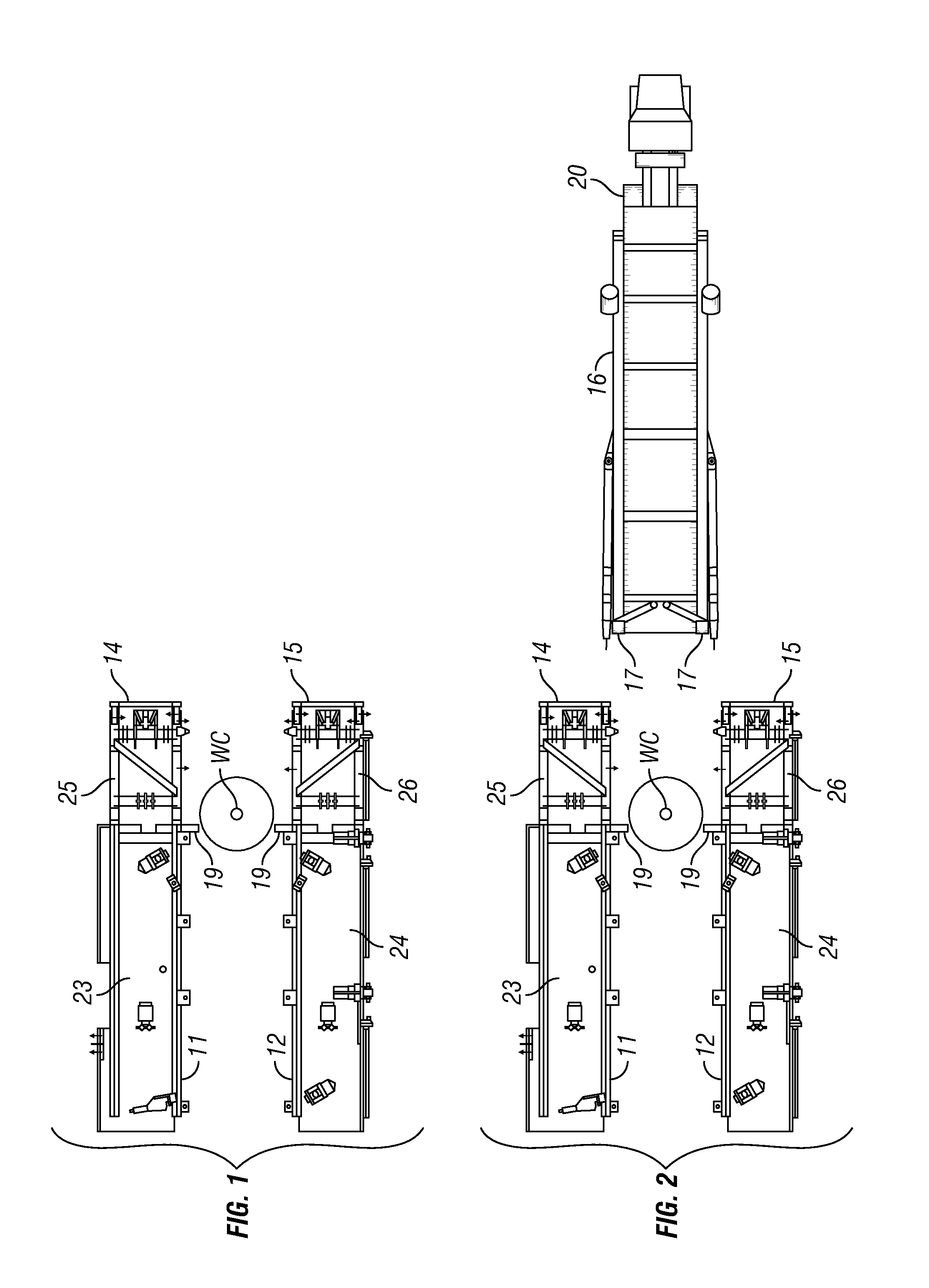
[0052]As shown in FIG. 1 two substructure side boxes 11, 12 of a rig according to the present invention are positioned with respect to a well center WC. In one aspect the substructure side box 11 is an Off-Drillers Side substructure side box and the substructure side box 12 is a Drillers Side substructure side box. The side box 11 has an upper box 23 and a lower box 25. The side box 12 has an upper box 24 and a lower box 26.
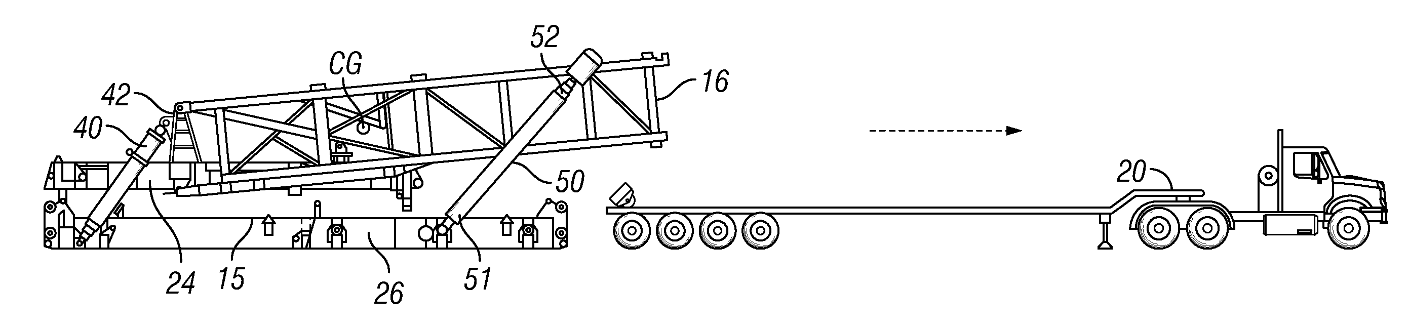
[0053]FIG. 2 illustrates the backing and the orienting of a truck 20 towards fronts 14, 15 of the substructure side boxes (“base boxes”) 11, 12, respectively. The truck 20 (a “mover”) carries a bottom mast section 16 with its feet 17 at the rear of the truck 20. In one aspect the truck 20 includes a cab / engine 20a which pulls a trailer 20b that supports the mast section 16. The truck 20 and the bottom mast section 16 are aligned with the well center.
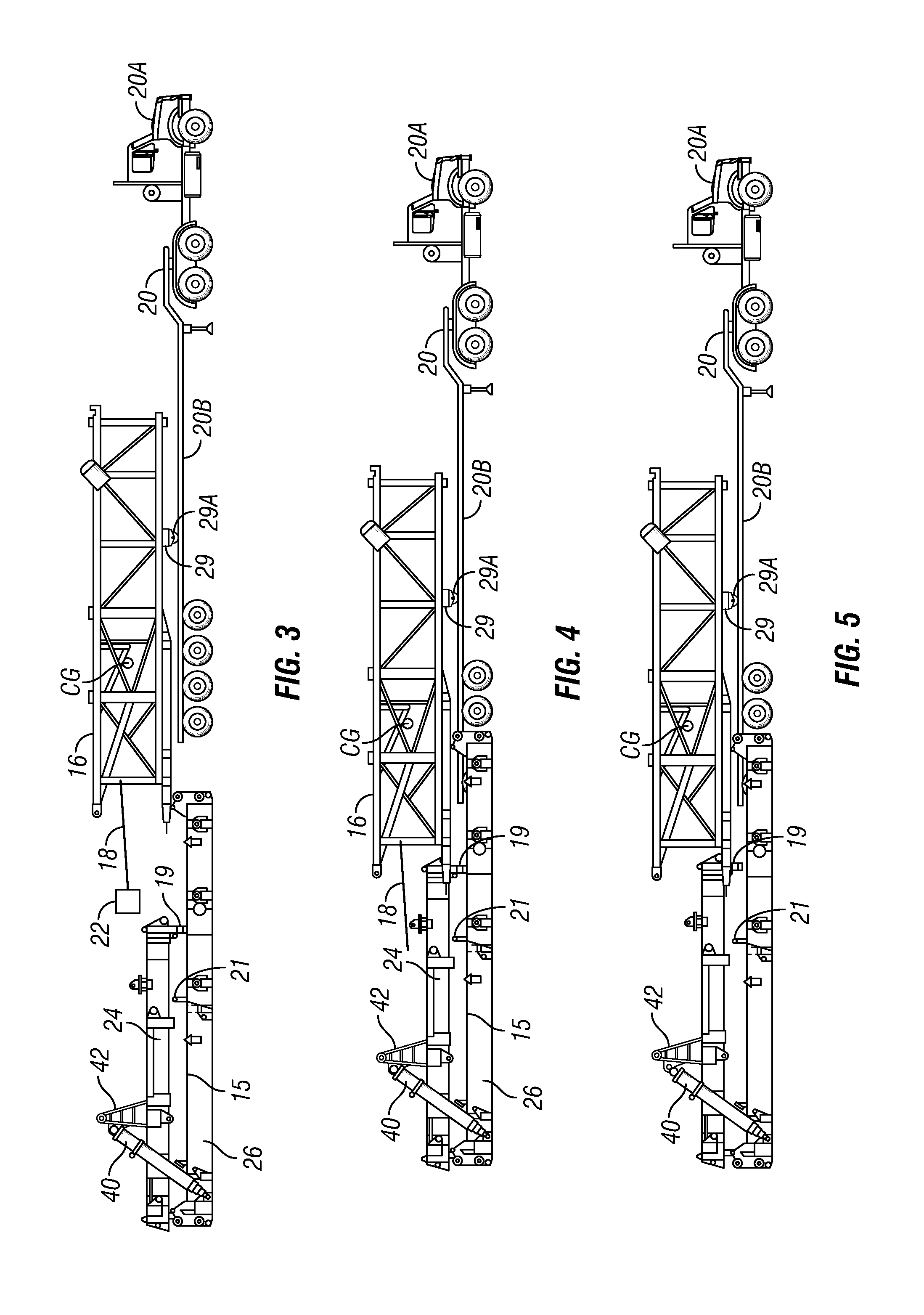
[0054]As shown in FIG. 3, a winch line 18 of a winch apparatus 22 (shown schematically in FIG. 3) is attached to th...
PUM
 Abstract
Description
Claims
Application Information