Staged pilots in pure airblast injectors for gas turbine engines

a gas turbine engine and injector technology, applied in the direction of efficient propulsion technologies, machines/engines, lighting and heating apparatus, etc., can solve the problems of difficult thermal efficiency, low emissions operation, and easy external and internal carbon concerns in the circumferential space of ports

Active Publication Date: 2012-03-01
ROLLS ROYCE PLC
View PDF11 Cites 59 Cited by
  • Summary
  • Abstract
  • Description
  • Claims
  • Application Information

AI Technical Summary

Problems solved by technology

However, high temperature combustion also tends to increase the production of nitrogen oxides (NOX).
It is difficult to provide thermally efficient, low emissions operation over the widening range of conditions in gas turbine engine designs.
Additionally, during low power operating conditions, conventional staged fuel injectors only have fuel flowing through one of the staged fuel circuits.
These circumferentially spaced ports are prone to external and internal carbon concerns.
While pure airblast nozzles can provide for clean fuel combustion when the engine compressor is spooled up, difficulties can arise during engine startup.
However, during engine startup the compressor is not fully spooled up and thus the air pressures provided to the nozzle during engine startup are not always high enough to provide the necessary atomizing air blast.
Therefore, the amount of fuel atomized can be insufficient to initiate or sustain ignition.
Thus it can be quite difficult to start an engine using only traditional pure air blast nozzles.
Another problem during startup for traditional airblast nozzles is that when the startup air pressure is too low to fully atomize the fuel flowing from the nozzle, significant amounts of fuel can issue from the nozzle without being atomized.
Liquid fuel drooling from the nozzle constitutes waste of fuel and can cause poor emissions as well as complications that can arise from fuel pooling in undesirable locations of the engine.
However, piloted airblast nozzles tend to lack the superior thermal management inherent in pure airblast nozzles.
Piloted airblast nozzles also fail to achieve identical spray characteristics with pure airblast nozzles because the pressure atomizing circuit mixes with the airblast spray.
However, while these solutions can be used to facilitate engine start up, they can also add significantly to the cost and weight of the engine.

Method used


Image

  • Staged pilots in pure airblast injectors for gas turbine engines
  • Staged pilots in pure airblast injectors for gas turbine engines
  • Staged pilots in pure airblast injectors for gas turbine engines

Examples


Embodiment Construction

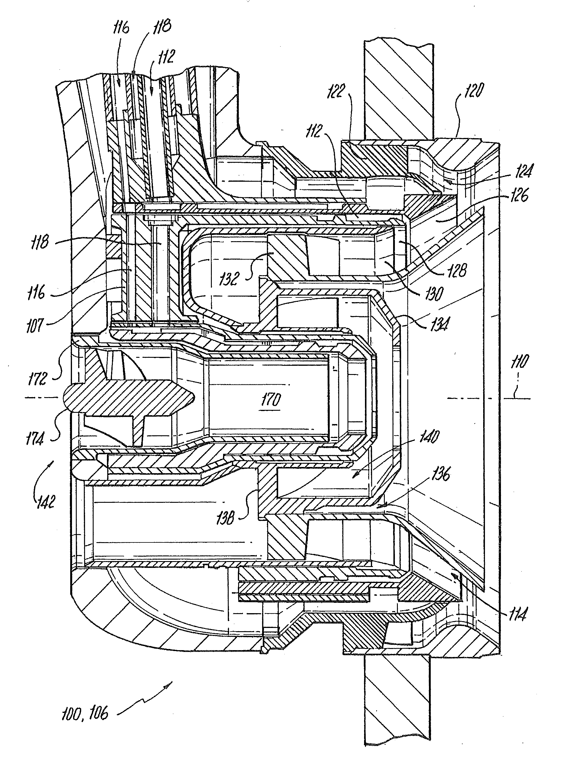
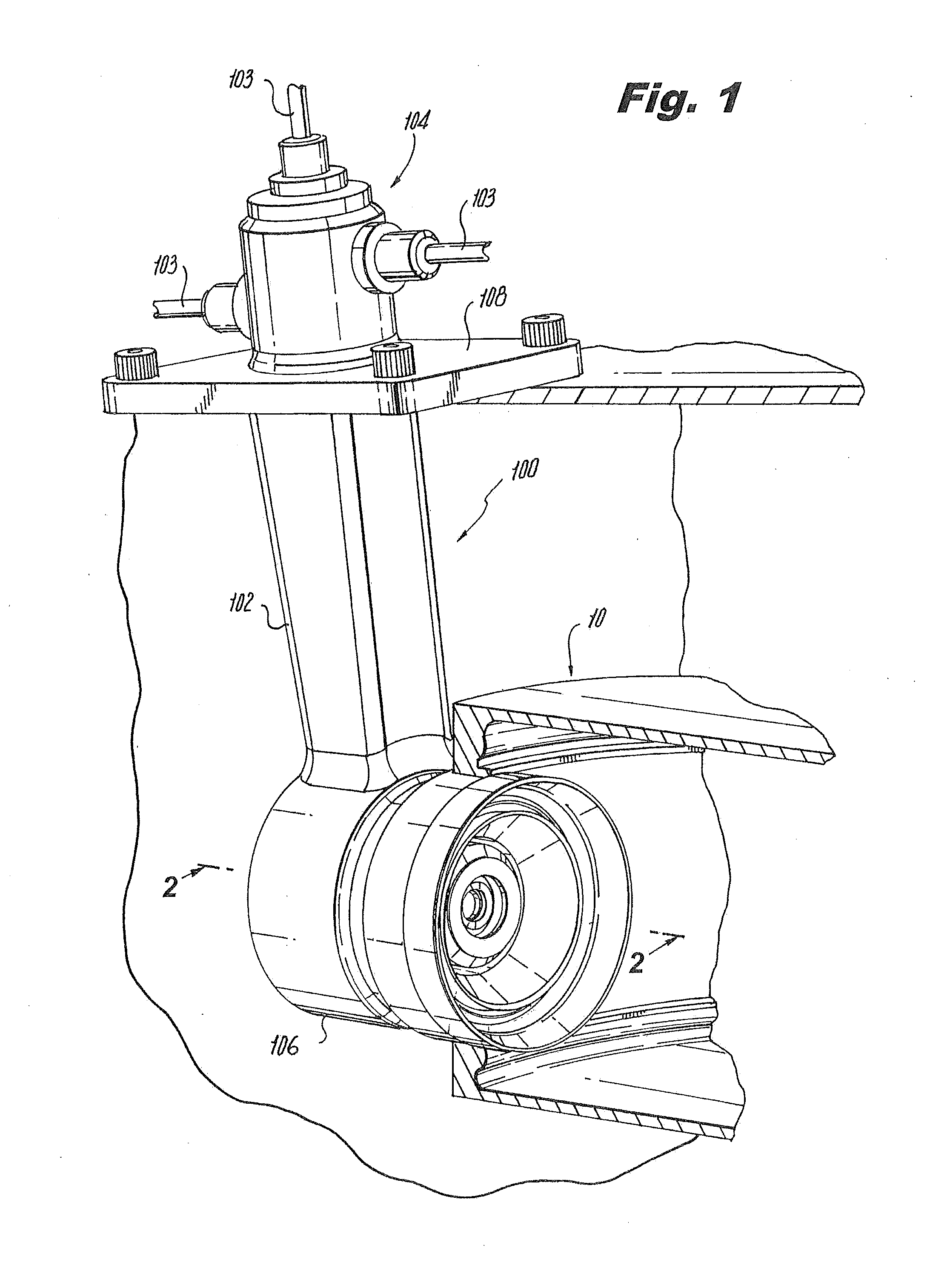
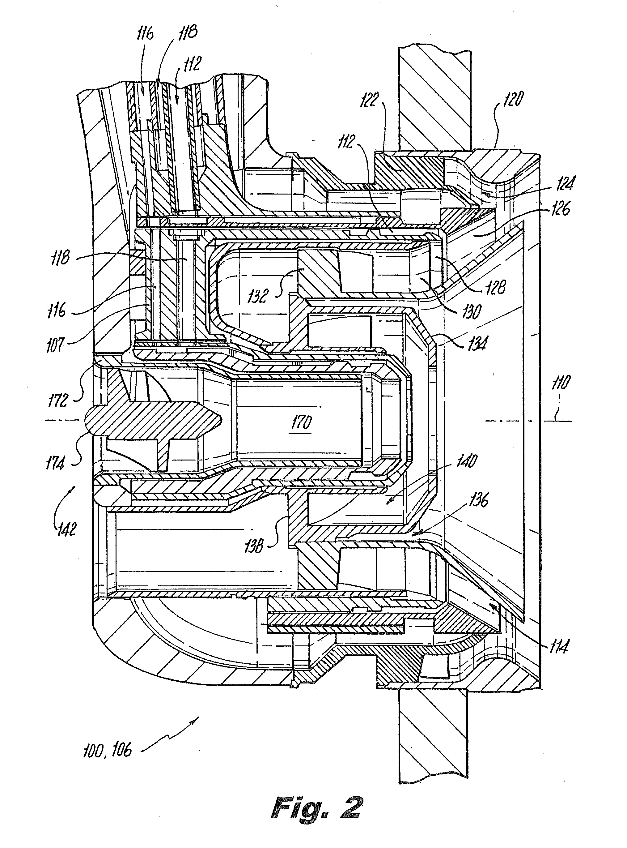
[0037]Reference will now be made to the drawings wherein like reference numerals identify similar structural features or aspects of the subject invention. For purposes of explanation and illustration, and not limitation, a partial view of an exemplary embodiment of an injector constructed in accordance with the invention is shown in FIG. 1 and is designated generally by reference character 100. Other embodiments of injectors in accordance with the invention, or aspects thereof, are provided in FIGS. 2-9, as will be described. The systems of the invention can be used to improve staging pressure ratios for lean direct injection, and to enhance fuel distribution at low power levels for improved startup.

[0038]U.S. Patent Application Publication No. 2006 / 0248898, which is incorporated herein by reference in its entirety, describes lean direct injection atomizers for gas turbine engines. The present invention pertains to fuel injectors that deliver a fuel / air mixture into the combustion c...


PUM


Abstract

An injector includes a main nozzle body defining a central axis and having a main fuel circuit. A pilot nozzle body is mounted inboard of the main nozzle body. The pilot nozzle body includes a pilot air circuit on the central axis with fuel circuitry radially outboard of the pilot air circuit for delivering fuel to a fuel outlet in a downstream portion of the pilot nozzle body. The fuel circuitry includes a primary pilot fuel circuit configured and adapted to deliver fuel to the fuel outlet and a secondary pilot fuel circuit configured and adapted to deliver fuel to the same fuel outlet.

Description

CROSS-REFERENCE TO RELATED APPLICATIONS[0001]This application is a continuation-in-part of U.S. patent application Ser. No. 12 / 115,579 filed May 6, 2008. This application is also a continuation-in-part of U.S. patent application Ser. No. 12 / 562,398 filed Sep. 18, 2009. Each of the two above-referenced applications is incorporated by reference herein in its entirety.BACKGROUND OF THE INVENTION[0002]1. Field of the Invention[0003]The present invention relates to injectors and atomizers, and more particularly to staged pilot fuel injectors for gas turbine engines.[0004]2. Description of Related Art[0005]A variety of devices and methods are known in the art for injecting fuel into gas turbine engines. Of such devices, many are directed to injecting fuel into combustors of gas turbine engines while reducing undesirable emissions. With the increased regulation of emissions from gas turbine engines have come a number of concepts for reducing pollutant emissions while improving the efficien...

Claims


Application Information

Patent Timeline
Patent Type & Authority Applications(United States)
IPC IPC(8): F02C7/22
CPCF02C7/22F02C7/222F02C7/228F02C9/34F23D11/107Y02T50/675F23D2900/11101F23R3/14F23R3/286F23R3/343F23D2900/00015Y02T50/60
Inventor WILLIAMS, BRANDON P.CHOLVIBUL, VIRAPHANDBRETZ, DAVID H.
Owner ROLLS ROYCE PLC
Why Eureka
Try Eureka