
Urine Flow Monitoring Device and Method

Active Publication Date: 2012-03-01
BELOTSERKOVSKY EDWARD
View PDF2 Cites 9 Cited by
  • Summary
  • Abstract
  • Description
  • Claims
  • Application Information

AI Technical Summary

Benefits of technology

[0009]The present invention is based in part on the recognition that during urination (or voiding process) the unique characteristic sounds that are produced by the urine as it impacts the surface of the water in a toilet or urinal can be used to monitor the person's urinary flow pattern and its dynamics. Specifically, because the sound's intensity (loudness) and spectrum depend on the urine flow level, by detecting the intensity at selected acoustic frequencies, it is possible to accurately and precisely measure the urine flow rate.
[0010]In a preferred embodiment, the present invention is directed to techniques for analyzing urine flow and its dynamics by using sound levels that are detected at two or more distinct frequency regions or channels of the sound spectrum. One frequency region that is designated the measurement channel is where the sound measurement intensity or output strongly depends on urine flow levels. Another frequency region that is designated the reference channel is where the sound measurement intensity is not dependent on urine flow levels. By using a combination of measurements from the measurement channel and the reference channel, the urine flow monitoring apparatus of the present invention compensates for variations in operating conditions and other factors during use.

Problems solved by technology

Merely observing the patient void will usually not enable the urologist or physician to accurately assess the degree of prostate enlargement.
As is apparent, current urine flow meters are complex and often require the assistance of a clinician for proper use; moreover, the devices require a high degree of maintenance.

Method used


Image

  • Urine Flow Monitoring Device and Method
  • Urine Flow Monitoring Device and Method
  • Urine Flow Monitoring Device and Method

Examples


Embodiment Construction

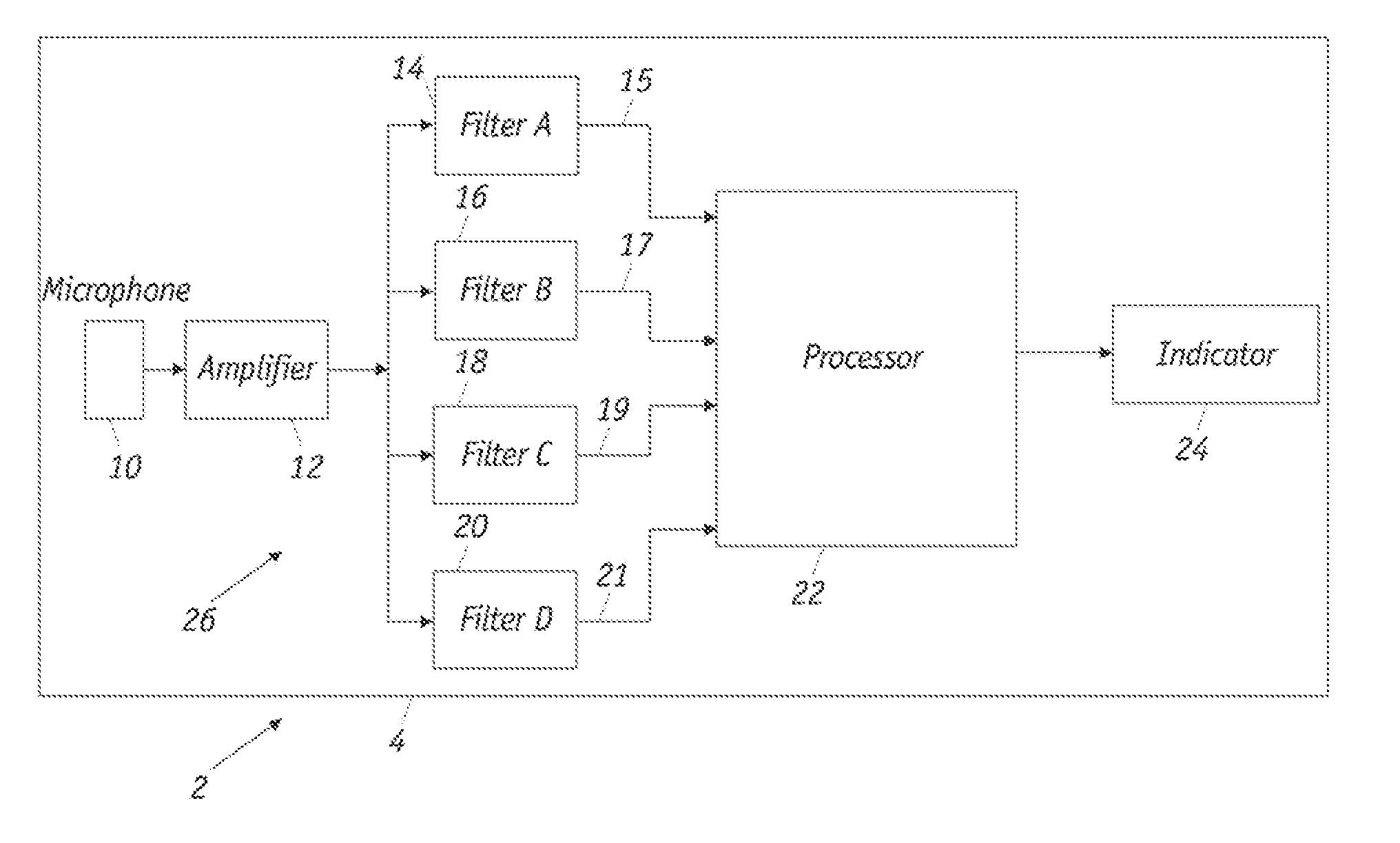
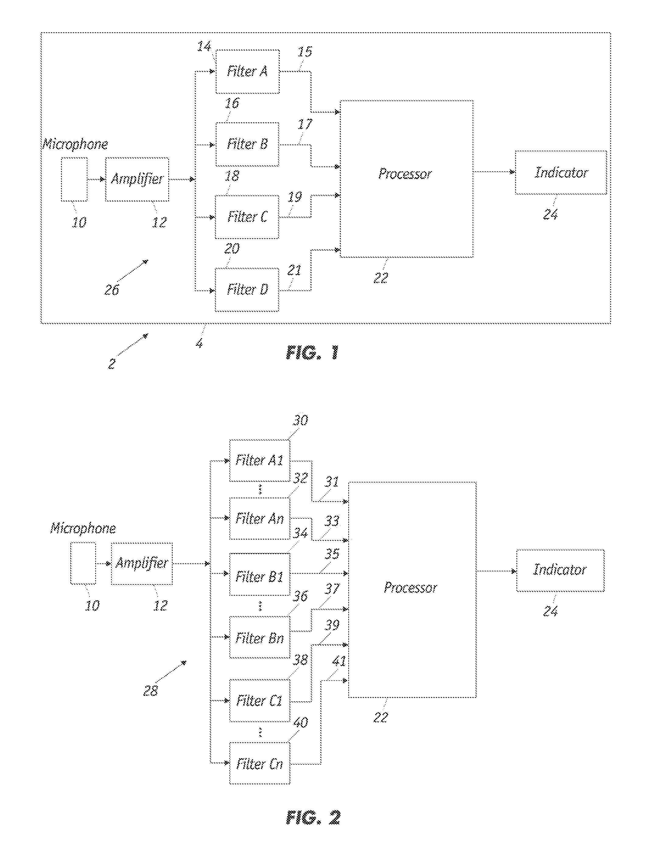
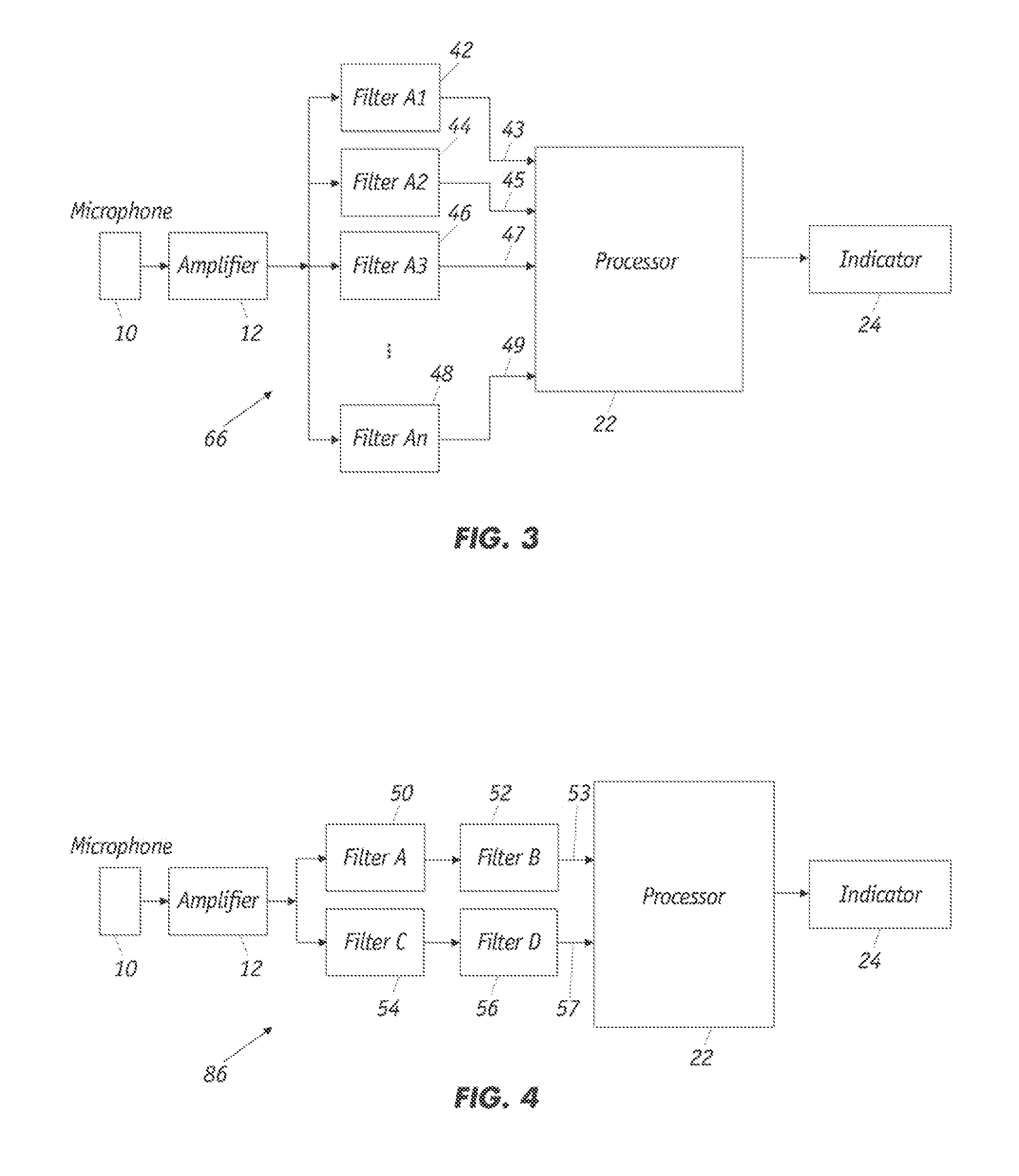
[0034]As shown in FIG. 1, the medical urine flow monitoring device 2 includes a housing 4 that encloses a microphone 10, amplifier 12, a bank of filters 26 that includes filters 14, 16, 18, and 20, a signal processor 22 and an output indicator 24. Electrical signals from microphone 10, which can be omnidirectional or unidirectional microphone(s), are amplified by amplifier 12 before being passed through a plurality of filters 14, 16, 18 and 20, that produce filtered signals 15, 17, 19, and 21, respectively. As further described herein, the bank of filters 26 serves to select the filtered signals of the desired frequency ranges to be analyzed by processor 22. The filters comprise one or more of a high-pass, low-pass, band-pass, and band-stop filter, for example, which are designated as Filters A, B, C and D, respectively. FIG. 1 depicts a four-channel urine flow-monitoring device with each channel employing a different type of filter. As further described herein, preferably one or mo...


PUM


Abstract

The unique characteristic sounds produced by urine as it impacts the surface of the water in a toilet are used to monitor men's urinary flow pattern and its dynamics. By detecting the intensity at selected acoustic frequencies, it is possible to accurately and precisely measure the urine flow rate. Techniques for analyzing urine flow and its dynamics employ sound levels that are detected at two or more distinct frequency regions or channels of the sound spectrum. One frequency region that is designated the measurement channel is where the sound measurement intensity strongly depends on urine flow levels. Another frequency region that is designated the reference channel is where the sound measurement intensity is not dependent on urine flow levels. By using a combination of measurements from the measurement channel and the reference channel, the urine-flow monitoring apparatus compensates for variations in operating conditions and other factors during use.

Description

REFERENCE TO RELATED APPLICATIONS[0001]This application claims priority, to U.S. Provisional Application 61 / 353,216 that was filed on Jun. 10, 2010.FIELD OF THE INVENTION[0002]The present invention generally relates to a medical apparatus for monitoring the discharge of urine by an individual. The apparatus gauges the volumetric flow and flow dynamics of the discharge, analyzes the data and displays the results.BACKGROUND OF THE INVENTION[0003]The prostate is a gland of the male reproductive system that is located in front of the rectum and just below the bladder. The prostate, comprised largely of muscular and glandular tissue, is wrapped around the urethra, which carries urine from the bladder out through the tip of the penis. Disorders of the prostate are fairly common during the aging process and include prostatitis, benign prostatic hyperplasia (BPH), and adenoma of the prostate, or prostate cancer. Prostatitis, which may or may not be the result of an infection, is generally d...

Claims


Application Information

Patent Timeline
IPC IPC(8): G01F1/66
CPCA61B5/202G01F1/666A61B2562/0204
Inventor BELOTSERKOVSKY, EDWARD
Owner BELOTSERKOVSKY EDWARD
Learn More