Bicycle Handlebar Grip

a handlebar and bicycle technology, applied in the direction of mechanical equipment, cycle equipment, steering devices, etc., can solve the problems of further relaxation of wrists, and achieve the effect of reducing flexibility of an outer reinforcement element or an outer area of a reinforcement element, reducing flexibility of the immediate adjoining outer area of the reinforcement element, and reducing the flexibility of the outer reinforcement elemen

Inactive Publication Date: 2012-03-01
RTI SPORTS VERTRIEB VON SPORTARTIKELN
View PDF9 Cites 13 Cited by
  • Summary
  • Abstract
  • Description
  • Claims
  • Application Information

AI Technical Summary

Benefits of technology

[0020]The flexibility of an outer reinforcement element or an outer area of a reinforcement element can be reduced by connecting this area of the mounted reinforcement element with the clamping means. When the clip-shaped clamping means is used the reinforcement element preferably extends into the slot of the clamping means, wherein a clamping element comprising a screw can then be guided through a bore provided in this area of the reinforcement element. When the sleeve is clampingly fastened to the bicycle handlebar, the reinforcement element is held or possibly even fixed in the slot of the clamping means. Thus the flexibility of the immediately adjoining outer area of the reinforcement element is reduced.
[0021]This offers the advantage that, when a plurality of reinforcement elements are provided, these elements cannot only be made from the same material but also have the same wall thickness and the flexibility of the outer reinforcement element is reduced due to a corresponding connection with the clamping means.
[0022]In a bicycle handlebar grip provided with a sleeve a reliable connection between the material surrounding the sleeve and / or the at least one reinforcement element can be improved in that preferably the sleeve and / or the at least one reinforcement element comprises recesses which are at least partly filled with the softer material surrounding the sleeve and / or the at least one reinforcement element. Here, it is particularly preferred that the fillings of the sleeve recesses protrude at least partly from an inner surface of the sleeve. This allows tolerances between the inner diameter of the sleeve and the outer diameter of the handlebar to be compensated for in a simple manner. Further, the soft material protruding inwards provides a better connection with the handlebar due to the increase in friction.

Problems solved by technology

This flexibility leads to a further relaxation of the wrists since in particular in this area large forces and shocks occur.

Method used


Image

  • Bicycle Handlebar Grip
  • Bicycle Handlebar Grip

Examples


Embodiment Construction

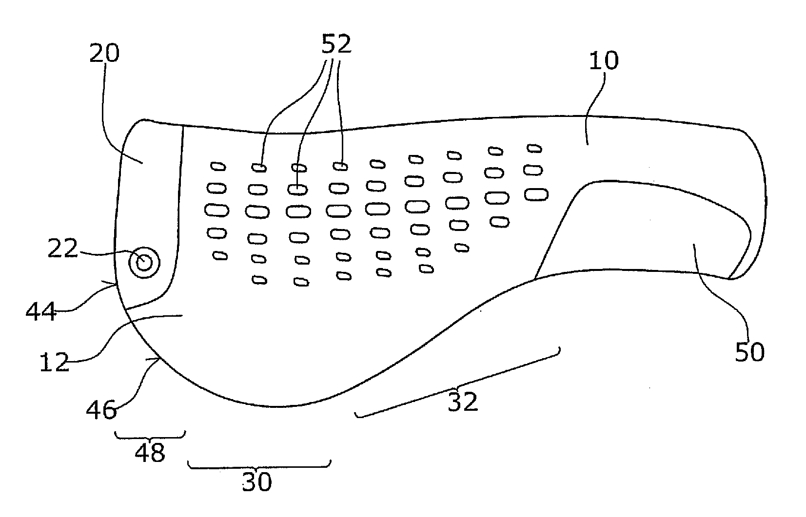
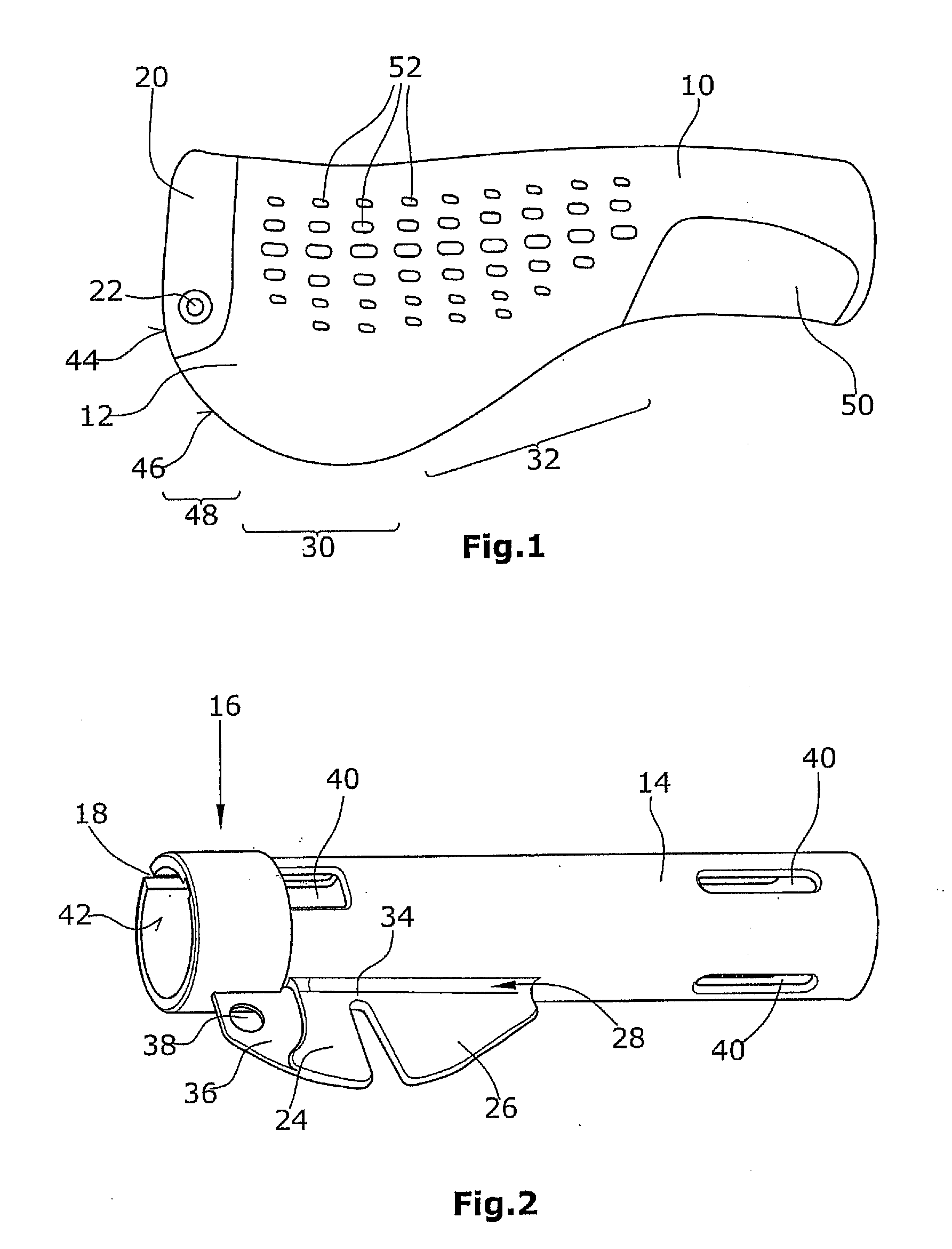
[0026]The bicycle handlebar grip according to the present invention comprises a grip element 10. Said grip element 10 is connected with a supporting element 12 for the heel of the hand (hereinafter referred to as supporting element 12). Said supporting element 12 extends towards the bicyclist such that the heel of the hand of the bicyclist can rest on the supporting element 12. The bicycle handlebar grip of FIG. 1, when mounted, is a left bicycle handlebar grip. The bicycle handlebar grip is fastened with the aid of sleeve 14 (FIG. 2) arranged inside the grip element 10 and the grip element 10 is injection-molded around said bicycle handlebar grip. A clamping area 16 of the sleeve 14 comprises a sleeve slot 18. In this area the sleeve 14 is surrounded by a clamping means 20 (FIG. 1). The clamping means which is of essentially ring-shaped configuration like a clip is adapted to be clamped with the aid of a screw 22. Thus in the clamping area 16 the inner diameter of the sleeve is red...


PUM


Abstract

A bicycle handlebar grip which is in particular suitable for mountain bikes and/or trekking bikes comprises a grip element (10) and a supporting element (12) for the heel of the hand connected with said grip element (10). The supporting element (12) for the heel of the hand comprises areas (30,32) of different flexibilities. In a preferred embodiment, the different flexibilities are realized by skeleton-type reinforcement elements (24,26) arranged inside the supporting element (12) for the heel of the hand.

Description

FIELD OF THE INVENTION[0001]The present invention relates to a bicycle handlebar grip and in particular to a bicycle handlebar grip for mountain bikes and trekking bikes.BACKGROUND OF THE INVENTIONDescription of the Prior Art[0002]During a bicycle ride the hand of the bicyclist is subjected to large stresses. This applies in particular when riding on uneven routes. These stresses frequently lead to aching wrists and numb fingers. Thus it has been common practice for a long time to configure bicycle handles such that they comprise, in addition to a grip element, a supporting element for the heel of the hand (hereinafter referred to as supporting element). Here, as with conventional bicycle handlebar grips, the grip element is of an essentially cylindrical configuration, for example, and, when mounted, surrounds the bicycle handlebar. The grip element has connected therewith the supporting element. The supporting element is a projection extending towards the bicyclist and allowing the...

Claims


Application Information

Patent Timeline
Patent Type & Authority Applications(United States)
IPC IPC(8): B62K21/26
CPCY10T74/20828B62K21/26
Inventor KRAUSE, ANDREASTOFAUTE, KIM
Owner RTI SPORTS VERTRIEB VON SPORTARTIKELN
Why Eureka
Try Eureka