
Oropharyngeal and nasopharyngeal airway having a breathing indicator

a technology of oropharyngeal and nasopharyngeal airway, which is applied in the direction of inhalators, medical devices, other medical devices, etc., can solve the problems of difficult to ascertain whether the person is effectively breathing, the patient may not be monitored as closely with respect to the continued operation of the device, and certain problems

Inactive Publication Date: 2012-03-01
YASICK ANTHONY JOHN
View PDF5 Cites 16 Cited by
  • Summary
  • Abstract
  • Description
  • Claims
  • Application Information

AI Technical Summary

Benefits of technology

[0024]In other preferred embodiments, the area of the passageway defined by the upper and lower flange portions is at least 80% the area of the passageway at the opening at the proximal end of the passageway body. Such a configuration is thought to allow contact with the reactive material while minimizing any obstruction to the flow of air.

Problems solved by technology

Once installed, the patient may not necessarily be monitored as closely with respect to the continued operation of the device.
Thus, certain problems can result.
Even in closely monitored patients, it can be difficult to ascertain as to whether the person is effectively breathing.
Obviously, if breathing issues persist, even for a short period of time, severe injury or death can result.
Other sensors are placed in equally large and cumbersome equipment that is generally configured to function with in-line devices.
As such, while there are some concerns as to size, typically, space is not at a premium, and there is ample space around which to place the detector.
Thus, the devices of the prior art are not suitable for use with airways, and would be difficult if not impossible to couple to an airway without degrading the performance of the airway.

Method used


Image

  • Oropharyngeal and nasopharyngeal airway having a breathing indicator
  • Oropharyngeal and nasopharyngeal airway having a breathing indicator
  • Oropharyngeal and nasopharyngeal airway having a breathing indicator

Examples


Embodiment Construction

[0057]While this disclosure is susceptible of embodiment in many different forms, there is shown in the drawings and described herein in detail a specific embodiment with the understanding that the present disclosure is to be considered as an exemplification and is not intended to be limited to the embodiment illustrated.

[0058]It will be understood that like or analogous elements and / or components, referred to herein, may be identified throughout the drawings by like reference characters. In addition, it will be understood that the drawings are merely schematic representations of the disclosure, and some of the components may have been distorted from actual scale for purposes of pictorial clarity.

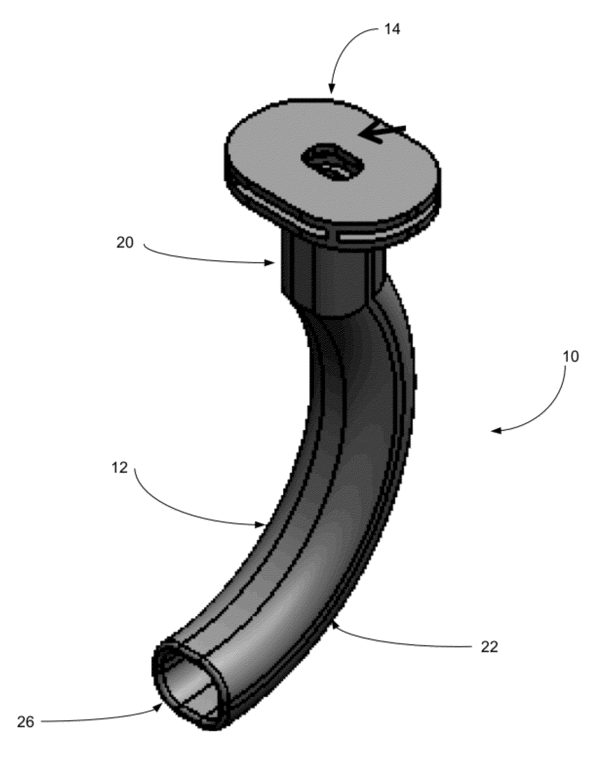
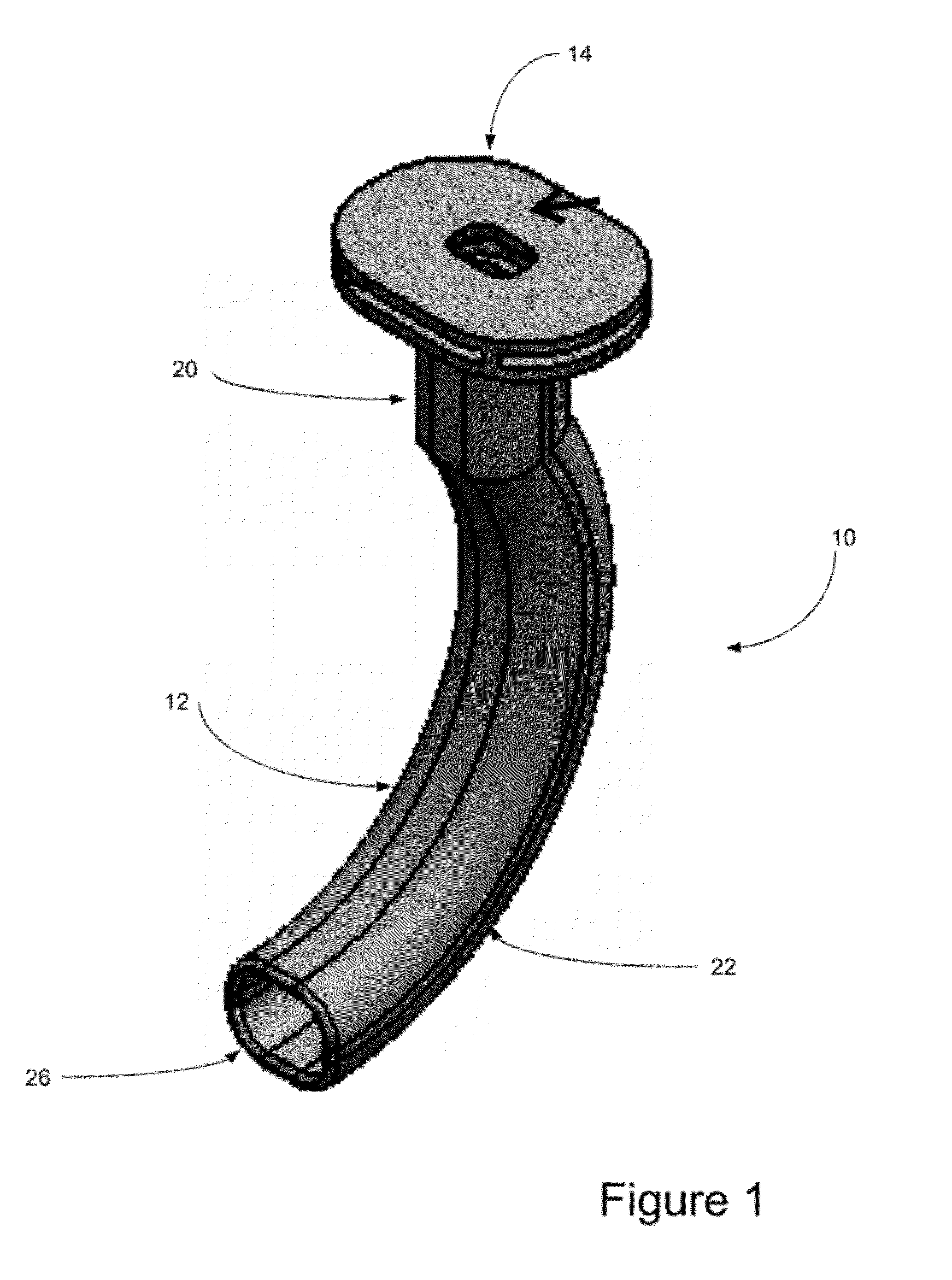
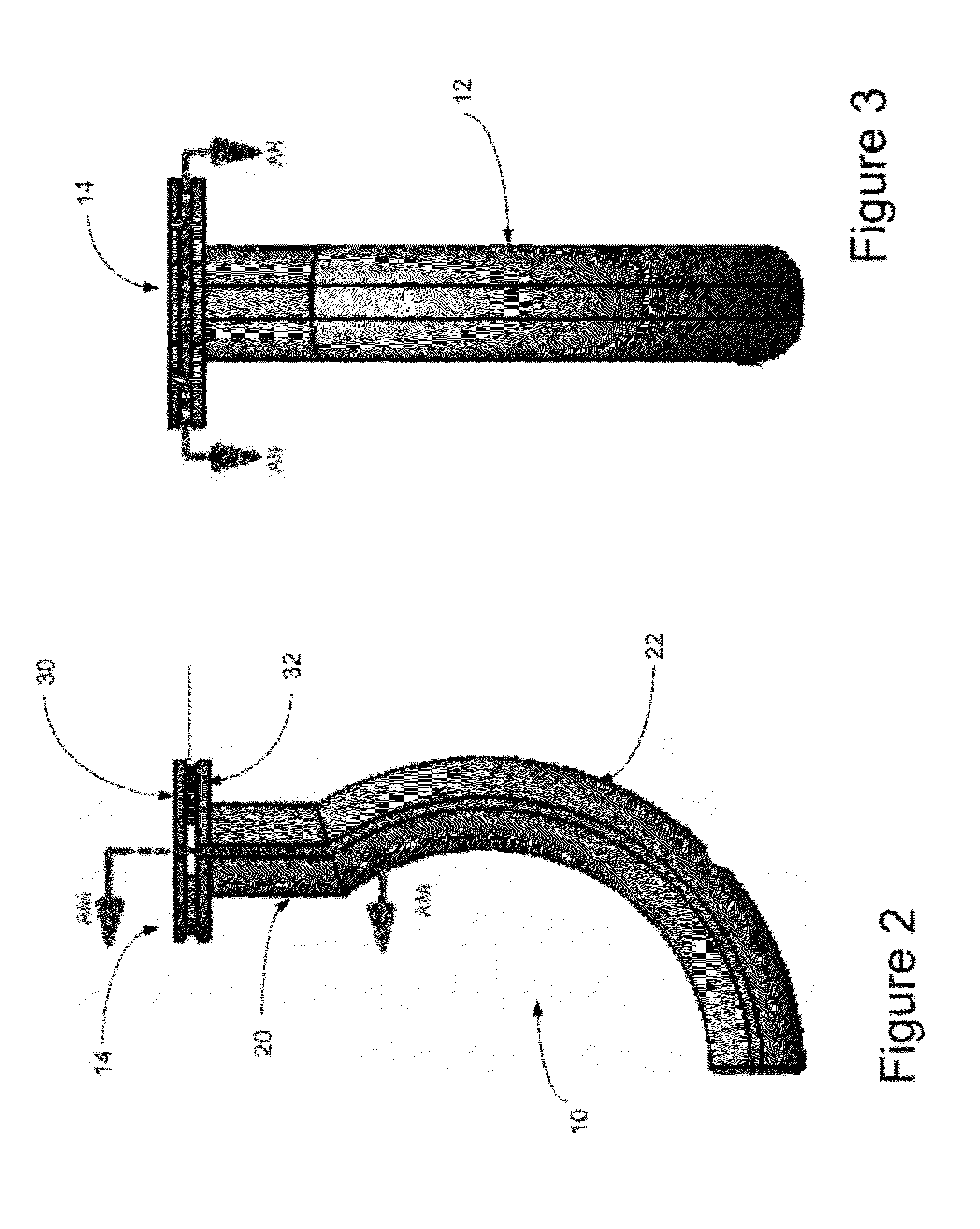
[0059]Referring now to the drawings and in particular to FIG. 1, an oropharyngeal airway is shown generally at 10. Typically, such airways come in a number of differently sized and shaped airways so as to accommodate the anatomical features of any number of differently sized individuals. In...


PUM


Abstract

An oropharyngeal airway configured for placement within a mouth of a patient to create a passageway between a mouth of a patient and the posterior pharyngeal wall that includes a passageway body, a flange assembly and a reactive material. The flange assembly is positioned at the end of the body and includes spaced apart upper and lower flange portions, which define a passageway therebetween which is in communication with the opening of the passageway body. The reactive material cooperates with the flange assembly and the passageway defined by the spaced apart flange portions. The reactive material provides qualitative visual indication as to whether the patient is effectively ventilating. A nasopharyngeal airway is likewise disclosed, as is a flange assembly which can be coupled to existing airways.

Description

CROSS-REFERENCE TO RELATED APPLICATION[0001]The present disclosure claims priority from U.S. Prov. Pat. App. Ser. No. 61 / 376, 340 filed Aug. 24, 2010, entitled “Oropharyngeal and Nasopharyngeal Airway Having an Indicator.” The entire disclosure of the provisional application is hereby incorporated by reference.BACKGROUND OF THE DISCLOSURE[0002]1. Field of the Disclosure[0003]The disclosure relates in general to airway adjuncts for maintaining an open airway of a patient, and more particularly, to an oropharyngeal or a nasopharyngeal airway having an indicator to confirm that the patient is effectively ventilating (also commonly referred to as effectively breathing), in a self-contained unit, even from a distance, and without difficulty.[0004]2. Background Art[0005]The use of a various airway adjuncts is well known in the art. Amongst a number of others, it is common to utilize either one of an oropharyngeal or a nasopharyngeal airway, especially in patients who are unconscious or se...

Claims


Application Information

Patent Timeline
IPC IPC(8): A61M16/04A61M16/00
CPCA61M16/04A61M16/0461A61M2016/0413A61M16/0493A61M2205/0238A61M2205/584A61M2205/0227A61M16/0495
Inventor YASICK, ANTHONY JOHN
Owner YASICK ANTHONY JOHN
Learn More