Integral buffering apparatus for automatically controlling flow rate of fluid and flat rack container including the integral buffering apparatus

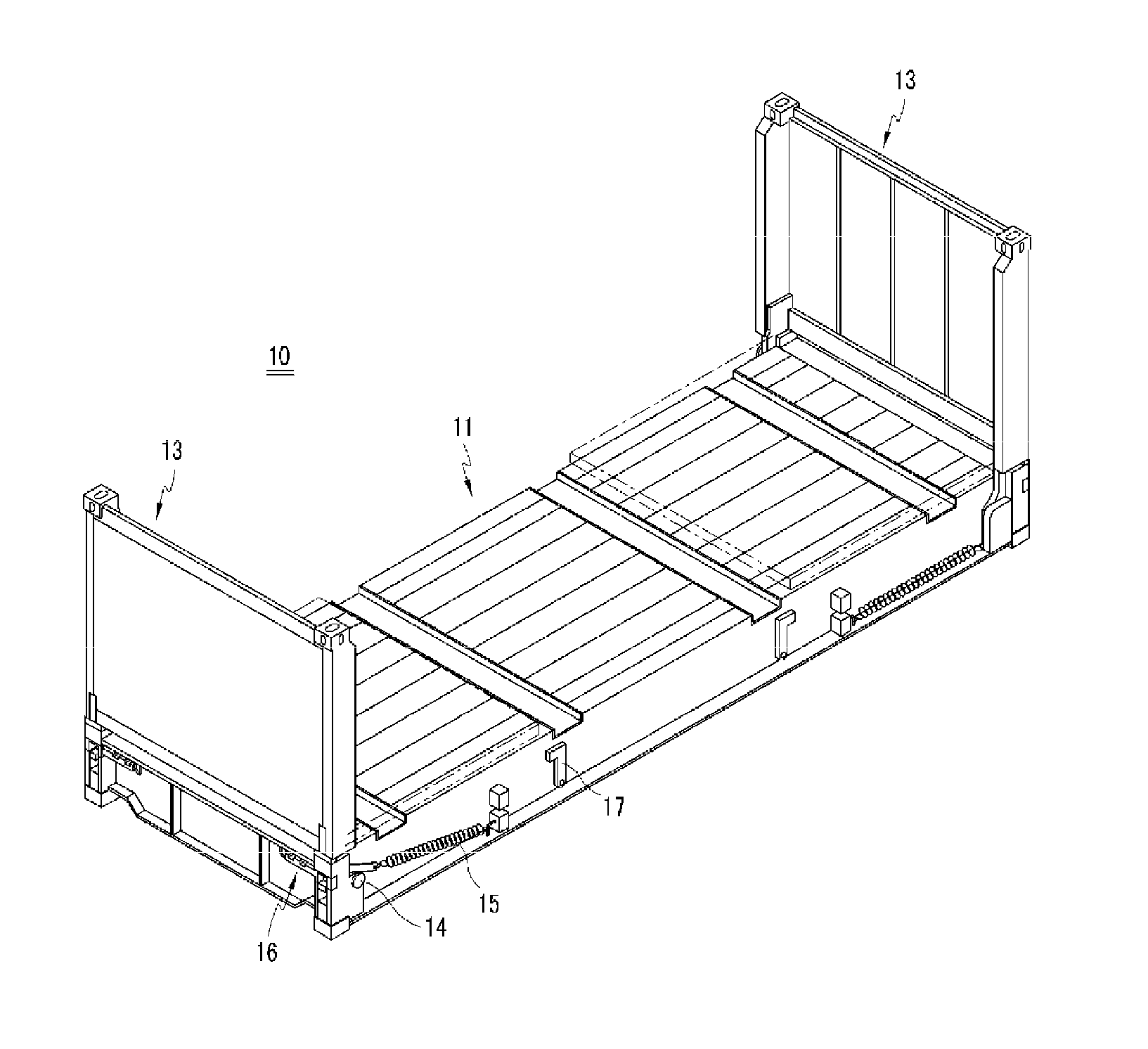
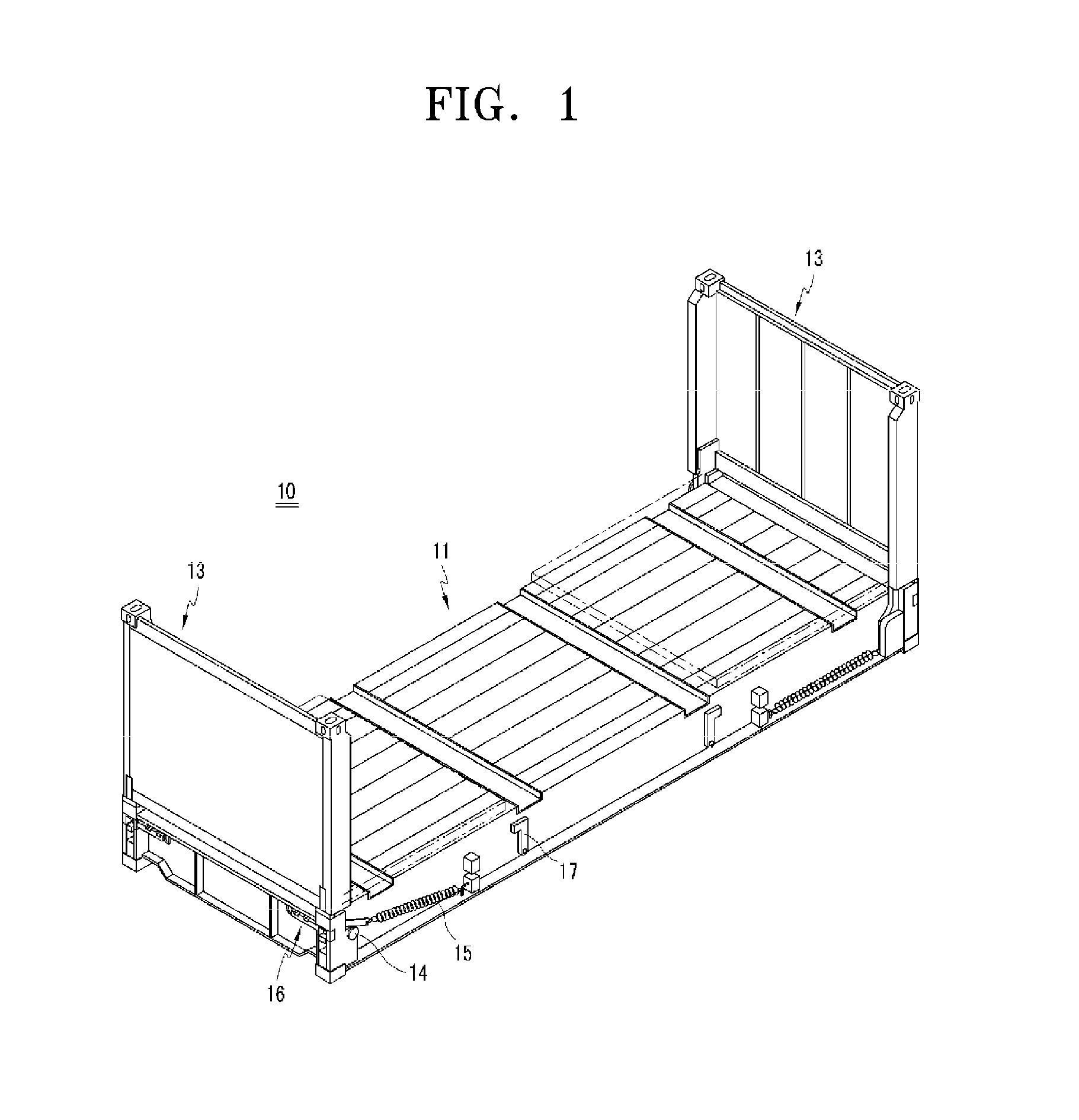
a technology of automatic control and fluid flow, which is applied in the field of flat rack containers, can solve the problems of excessive resistance force applied to the end wall b>13/b> when the end wall b>13/b> is folded, electrical equipment is additionally, and the safety of workers is not guaranteed, so as to prevent damage to the end wall and the base, reduce manufacturing costs, and facilitate folding. the effect of operation

Active Publication Date: 2012-03-01
VANPLUS
View PDF6 Cites 13 Cited by
  • Summary
  • Abstract
  • Description
  • Claims
  • Application Information

AI Technical Summary

Benefits of technology

[0017]The present invention provides an integral buffering apparatus for automatically controlling a flow rate of a fluid to control a falling speed of end walls, thereby absorbing an impact of the end walls, preve

Problems solved by technology

However, in this case, a resistive force applied to the end wall 13 when the end wall 13 is folded is excessively weak.
In addition, the impact may cause various safety accidents involving workers

Method used


Image

  • Integral buffering apparatus for automatically controlling flow rate of fluid and flat rack container including the integral buffering apparatus
  • Integral buffering apparatus for automatically controlling flow rate of fluid and flat rack container including the integral buffering apparatus
  • Integral buffering apparatus for automatically controlling flow rate of fluid and flat rack container including the integral buffering apparatus

Examples


Embodiment Construction

[0044]Hereinafter, the present invention will be described in detail by explaining embodiments of the invention with reference to the attached drawings.

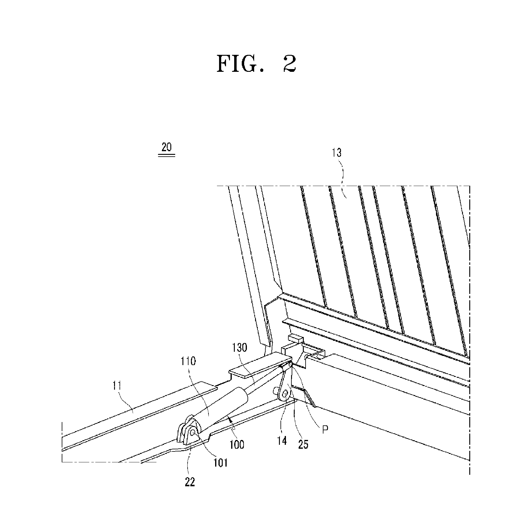
[0045]FIG. 2 is a perspective view of a flat rack container 20 including an integral buffering apparatus 100 for automatically controlling a flow rate of a fluid, according to an embodiment of the present invention. FIG. 3 is a front view for describing a folding operation of an end wall 13 of the flat rack container 20 illustrated in FIG. 2. FIG. 4 is an exploded perspective view of the integral buffering apparatus 100 illustrated in FIG. 2, according to an embodiment of the present invention. FIG. 5 is a combined perspective view of the integral buffering apparatus 100 illustrated in FIG. 4. FIG. 6 is a cross-sectional view for describing a hydraulic operation of the integral buffering apparatus 100 illustrated in FIG. 4 when the end wall 13 illustrated in FIG. 2 is folded. FIG. 7 is a cross-sectional view for describing the hydrau...


PUM


Abstract

The present invention relates to a flat rack container, and more particularly, to an integral buffering apparatus disposed between end walls and a base and for automatically controlling a flow rate of oil that flows in a cylinder housing through channels formed in a slider when the end walls are folded, to control a falling speed of the end walls, thereby absorbing an impact of the end walls, preventing damage of the end walls and the base, and ensuring safety of workers. The integral buffering apparatus includes a cylinder housing including a space for accommodating oil; a slider disposed in the space to be movable in a length direction of the cylinder housing and to divide the space into a first space and a second space; first oil channels and a second oil channel for connecting the first space and the second space to each other.

Description

BACKGROUND OF THE INVENTION[0001]1. Field of the Invention[0002]The present invention relates to a flat rack container, and more particularly, to an integral buffering apparatus disposed between end walls and a base and for automatically controlling a flow rate of oil that flows in a cylinder housing through channels formed in a slider when the end walls are folded, to control a falling speed of the end walls, thereby absorbing an impact of the end walls, preventing damage of the end walls and the base, and ensuring safety of a worker.[0003]2. Description of the Related Art[0004]In general, containers are used to conveniently transfer goods and their sizes are standardized by the International Organization for Standardization (ISO), e.g., 20 feet, 40 feet, and 45 feet.[0005]Examples of containers include dry containers, reefer containers, open top containers, and flat rack containers.[0006]From among these, flat rack containers do not have ceilings and side walls and thus medium-siz...

Claims


Application Information

Patent Timeline
IPC IPC(8): F16F9/516F16F9/50F16F9/19B65D88/12
CPCB65D88/129F16F9/516B65D88/522
Inventor CHOI, DU-MIN
Owner VANPLUS
Why Eureka
Try Eureka