

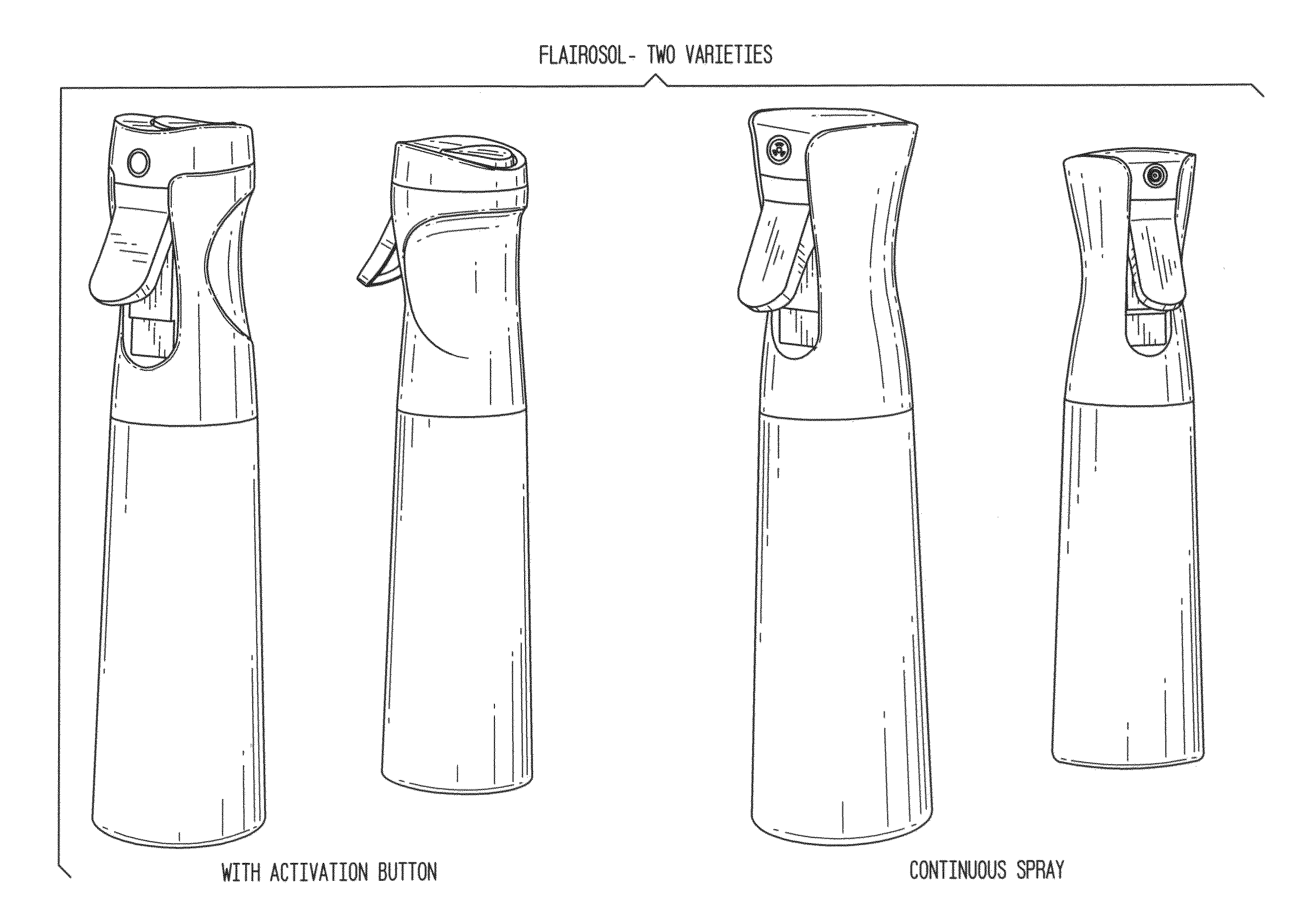
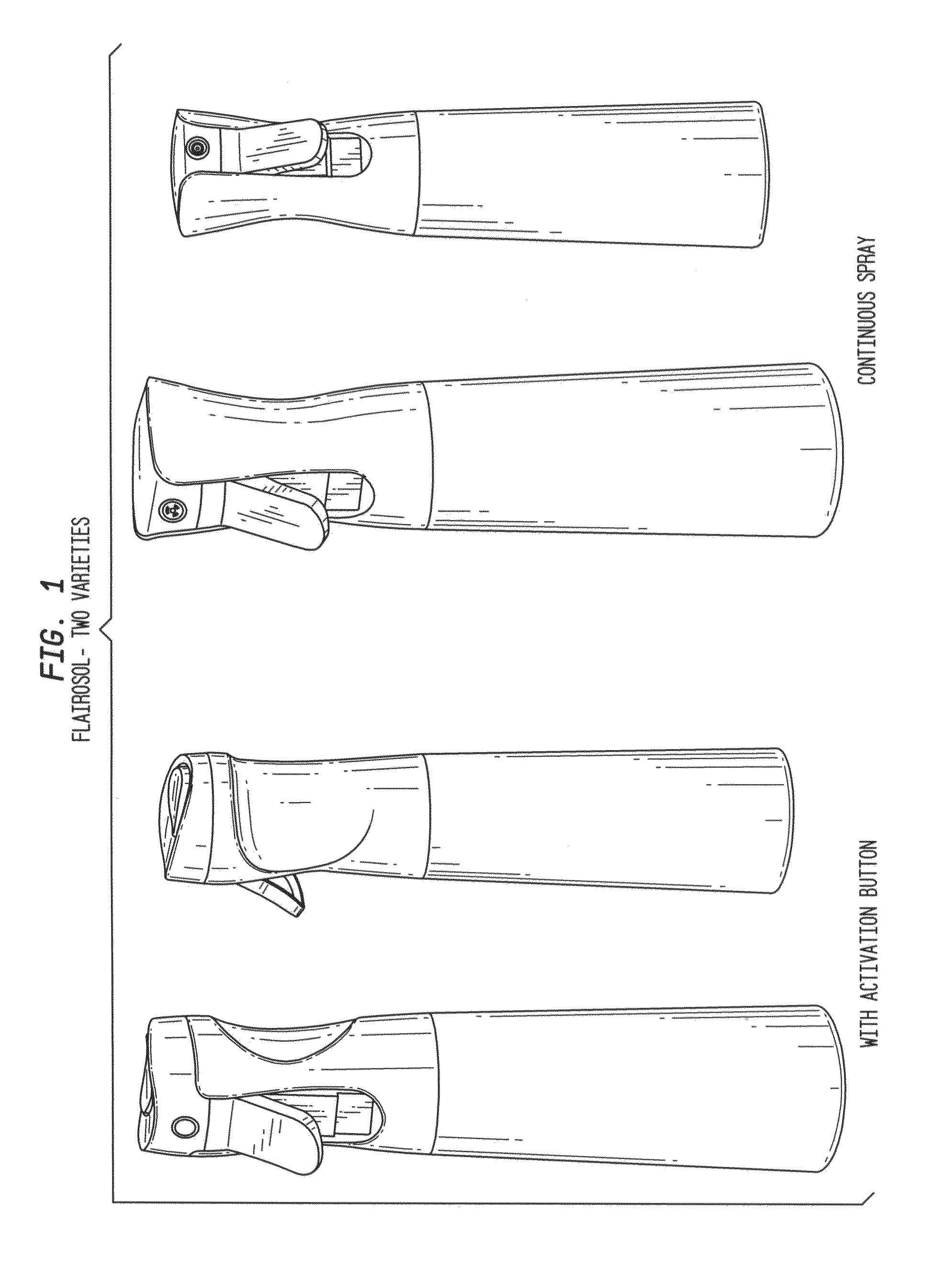
Sprayer device with aerosol functionality ("Flairosol")
a technology of aerosol and nozzle, which is applied in the direction of liquid handling, combustion types, instruments, etc., can solve the problems of requiring the use of non-environmental friendly materials and ingredients, and the environmental hazards of aerosols, so as to prevent backflow and prevent leakage
- Summary
- Abstract
- Description
- Claims
- Application Information
AI Technical Summary
Benefits of technology
Problems solved by technology
Method used
Image

Examples
Embodiment Construction
[0024]In exemplary embodiments of the present invention, a liquid spraying device offers the benefits of both a liquid sprayer and an aerosol device. Such an exemplary device is referred to herein as a “Flairosol” device, given that it uses the “bag within a bag” Flair® technology developed and provided by Dispensing Technologies B.V. of Helmond, The Netherlands, and combines that technology with means to internally pressurize the liquid prior to spraying so as to emulate aerosol devices.
[0025]It is noted that the functionalities described herein could, for example, be implemented without Flair®“bag within a bag” technology, and thus exemplary embodiments of the present invention are not strictly limited thereto. However, such a non-Flair® technology implementation would be more expensive and more cumbersome to produce and use. The “bag within a bag” Flair® technology, which causes the inner container to shrink around the pressure chamber and input tube, and thus obviates headspace ...
PUM
 Abstract
Description
Claims
Application Information