Defective recording element correction parameter selection chart, defective recording element correction parameter determination method and apparatus, and image forming apparatus

a recording element and correction parameter technology, applied in the direction of printing, power drive mechanisms, printing mechanisms, etc., can solve the problems of large disparity between the tones read by a scanner and human visual characteristics, the measurement accuracy of the correction parameter for ejection failure is expected to decline, and the nozzle is in a state of ejection failure due to blockage or breakdown, so as to improve the correction performance of an image formation defect caused by a defective recording element and achieve the effect of improving the output image quality and high accuracy

Active Publication Date: 2012-03-01
FUJIFILM CORP
View PDF3 Cites 32 Cited by
  • Summary
  • Abstract
  • Description
  • Claims
  • Application Information

AI Technical Summary

Benefits of technology

[0075]According to the present invention, it is possible to measure a defective recording element correction parameter with high accuracy, compared to a conventional method. By this means, the correction performance in respect of an image formation defect caused by a defective recording element is improved, and improvements in output image quality can be achieved.

Problems solved by technology

In image formation by an inkjet method, when the inkjet head starts to be used, nozzles which are in a state of ejection failure due to blockages or breakdown occur.
However, in the method described in Japanese patent application publication No. 2008-168592, the measurement accuracy of the ejection failure correction parameter is expected to decline due to the following factors.
There is a large disparity between the tones read by a scanner and human visual characteristics.
The measurement accuracy declines due to the combination of these.
Moreover, the visibility varies greatly due to various factors, such as the position error, dot diameter variation, landing interference, and the like, in the vicinity of the ejection failure nozzle.
If the test pattern (chart) is output by an inkjet printer, then image non-uniformities occur due to the effects of positional error, ejection non-uniformities, and other factors.
This is a cause of error in the measurement of the ejection failure correction parameter on the basis of the output results of the test pattern.
In a method which measures the average tone value as in the procedure described in Japanese patent application publication No. 2008-168592, it is not possible to eliminate the effects of image non-uniformities entirely.

Method used


Image

  • Defective recording element correction parameter selection chart, defective recording element correction parameter determination method and apparatus, and image forming apparatus
  • Defective recording element correction parameter selection chart, defective recording element correction parameter determination method and apparatus, and image forming apparatus
  • Defective recording element correction parameter selection chart, defective recording element correction parameter determination method and apparatus, and image forming apparatus

Examples


first embodiment

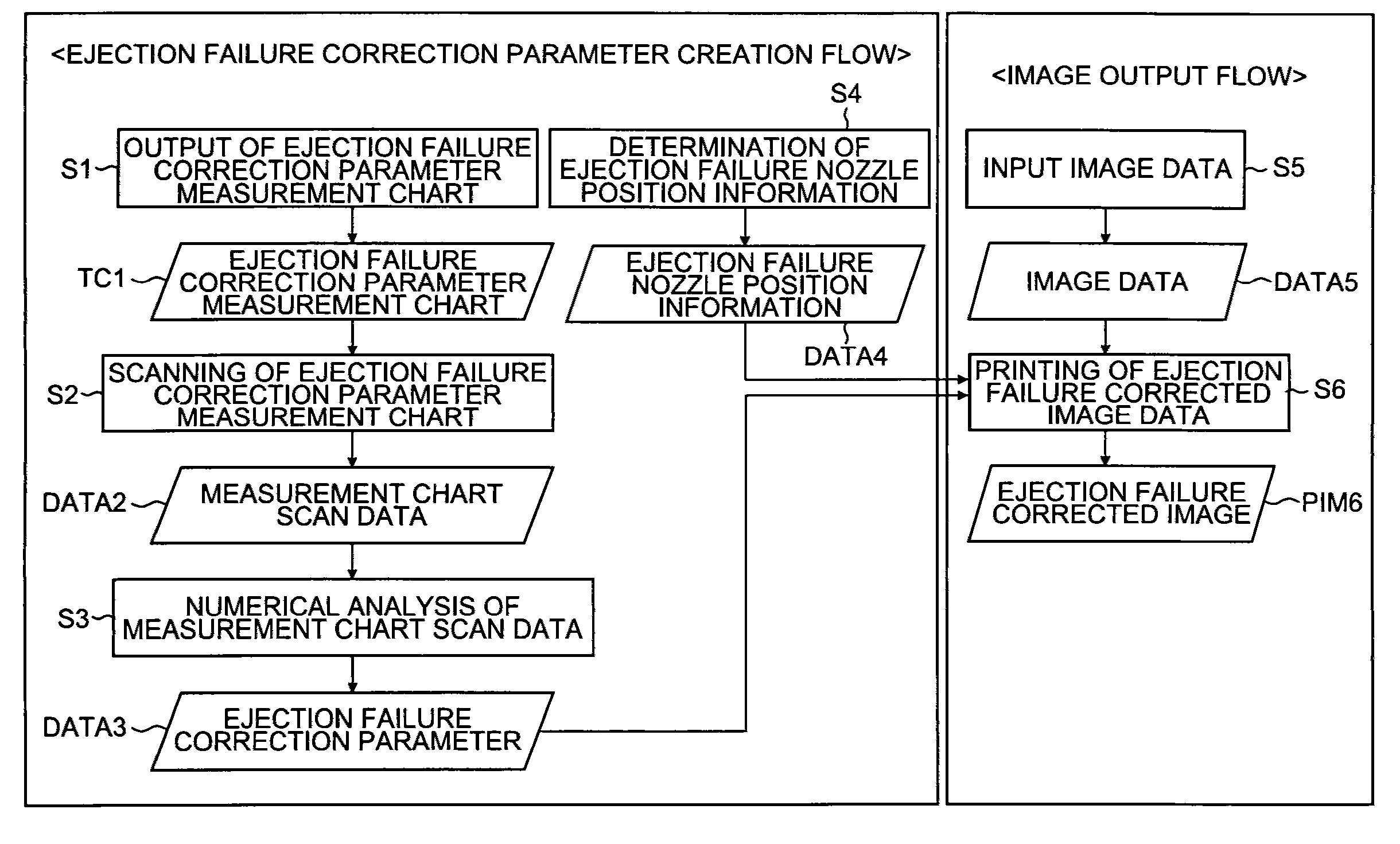
[0108]FIG. 1 is a flowchart of an ejection failure correction method relating to a first embodiment of the present invention. The ejection failure correction processing according to the present embodiment is divided broadly into an “ejection failure correction parameter creating flow” for acquiring information about a correction parameter required to correct ejection failure, and an “image output flow” for implementing correction processing using this to correction parameter.

Description of Ejection Failure Correction Parameter Creation Flow

[0109]In the ejection failure correction processing according to the present embodiment, firstly, [1] a measurement chart for selecting an optimal value of the ejection failure correction parameter (hereinafter, this measurement chart may be called the “ejection failure correction parameter optimal value selection chart” or simply “optimal value selection chart”) is output (step S1). The optimal value selection chart (TC1) which is output in this ...

second embodiment

[0138]As shown in FIG. 4, if the print head 2 is constituted by a plurality of head modules (j=1, 2, . . . , N), then an ejection failure correction parameter optimal value selection chart as described in the first embodiment (see FIG. 4) is formed in the image formation regions corresponding to the respective head modules 1—j (j=1, 2, . . . , N), and similar analysis to that of the first embodiment is carried out in respect of each head module 1—j (j=1, 2, . . . , N). By this means, the ejection failure correction parameter is optimized for each head module, and variation in the visibility of the correction results, as described in relation to FIG. 31B, can be overcome.

third embodiment

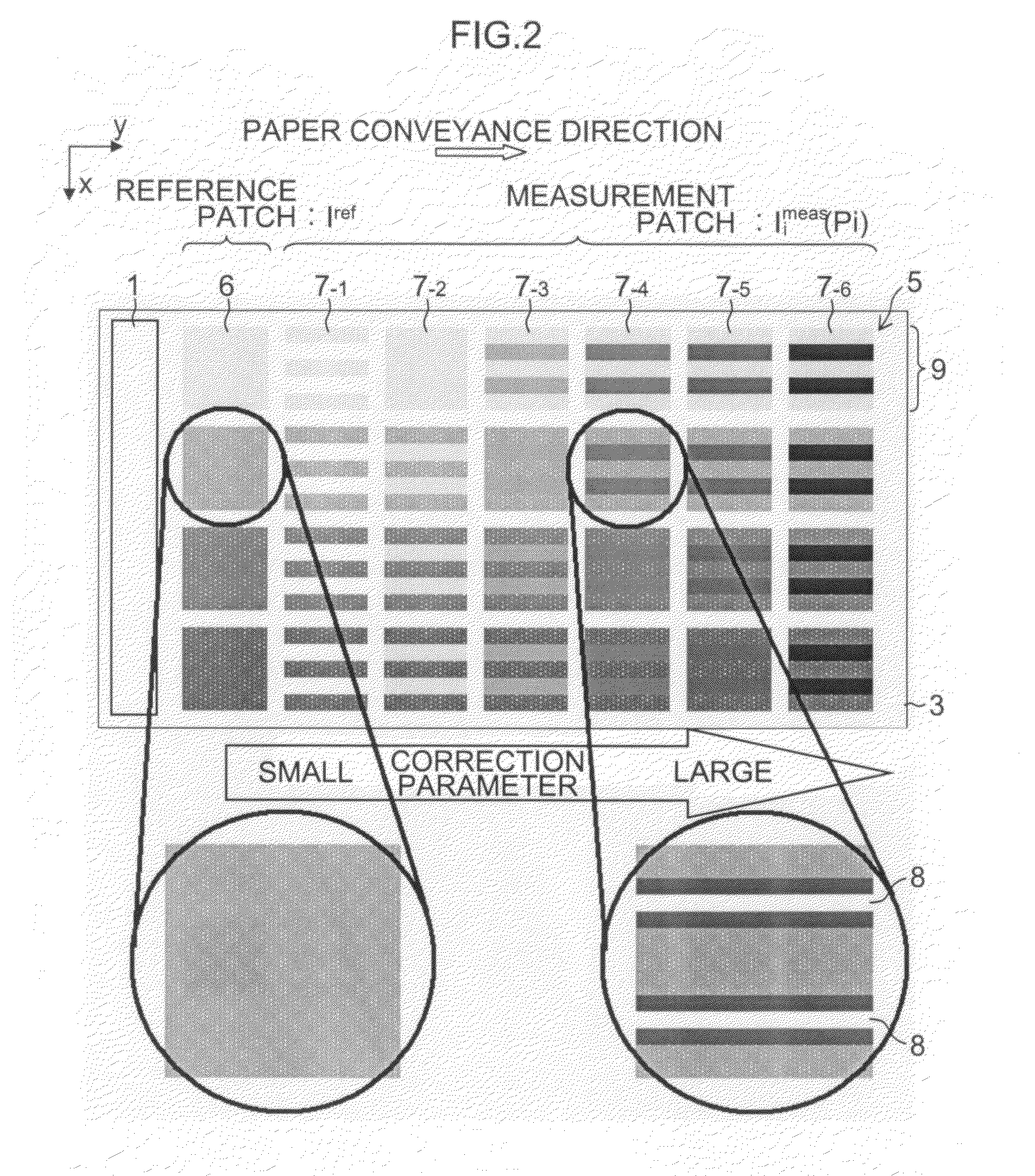
[0139]Instead of the arrangement of patches in the ejection failure correction parameter optimal value selection chart according to the first embodiment which is described in relation to FIG. 2, it is also possible to employ a mode in which a reference patch 6 is disposed in the vicinity of the center of the alignment of measurement patches 7—i (i=1, 2, . . . , 6), as shown in FIG. 5.

[0140]In scanning the optimal value selection chart, skew is liable to occur depending on the positioning of the paper during scanning. Furthermore, during image formation, a small angular difference may occur between the print head and the paper, depending on the relative positional relationship between the head and the paper. Due to these factors, skew occurs in the scan data of the optimal value selection chart. The effects of the skew become less influential, the smaller the distance between the reference patch 6 and each measurement patch 7—i (i=1, 2, . . . , 6) of the same tone value L. Consequent...


PUM


Abstract

A defective recording element correction parameter selection chart which is output by an image forming apparatus that performs image formation on a recording medium by a plurality of recording elements included in a recording head while conveying at least one of the recording head and the recording medium so as to cause relative movement between the recording head and the recording medium, the chart being used, in a case where there is at least one defective recording element which is not able to perform recording among the plurality of recording elements, in order to determine a defective recording element correction parameter expressing an amount of correction for correcting image formation defects caused by the at least one defective recording element, with image formation by a recording element other than the at least one defective recording element, the chart includes: a reference patch constituted by a uniform image which is an image formed on a region of the recording medium with a uniform density based on a constant tone; and at least one measurement patch in which a state after correction using the amount of correction corresponding to a candidate value of the defective recording element correction parameter which expresses the amount of correction is reproduced in a state that one or more of the recording elements which have formed the reference patch are set to be in a non-recording state, the candidate value of the defective recording element correction parameter being applied to an image formation portion which is formed by a recording element that carries out recording in a vicinity of a non-recording position of the one or more of the recording elements which have formed the reference patch and have been set to be in the non-recording state.

Description

BACKGROUND OF THE INVENTION[0001]1. Field of the Invention[0002]The present invention relates to correction technology for improving image formation defects caused by defective recording elements in a recording head having a plurality of recording elements, such as an inkjet head, and more particularly, to a parameter selection chart suitable for determining a parameter to be used in correction processing, and a parameter determination method, a parameter determination apparatus and an image forming apparatus using the parameter selection chart.[0003]2. Description of the Related Art[0004]In image formation by an inkjet method, when the inkjet head starts to be used, nozzles which are in a state of ejection failure due to blockages or breakdown occur. In particular, in the case of image formation by a single pass method, the ejection failure nozzle locations are perceived as white stripes and therefore the correction is required. There have been a large number of suggestions thus fa...

Claims


Application Information

Patent Timeline
Patent Type & Authority Applications(United States)
IPC IPC(8): B41J29/393
CPCB41J2/04501B41J2/16579B41J2/2146B41J2/2142B41J2/2139B41J2025/008
Inventor UESHIMA, MASASHI
Owner FUJIFILM CORP
Why Eureka
Try Eureka