Geometric calibration of head-worn multi-camera eye tracking system

Inactive Publication Date: 2012-03-01
SIEMENS MEDICAL SOLUTIONS USA INC
View PDF3 Cites 285 Cited by
  • Summary
  • Abstract
  • Description
  • Claims
  • Application Information

AI Technical Summary

Benefits of technology

[0021]In accordance with yet a further aspect of the present invention the method is provided, wherein the processor estimates the parameters of the of the geometric model of the eye by minimizing a projection error of an estimated intersection point of the direction of gaze with the displa

Problems solved by technology

For vision applications needing both precise measurements and comfortable use, no known system currently exists that calibrates the

Method used


Image

  • Geometric calibration of head-worn multi-camera eye tracking system
  • Geometric calibration of head-worn multi-camera eye tracking system
  • Geometric calibration of head-worn multi-camera eye tracking system

Examples


Embodiment Construction

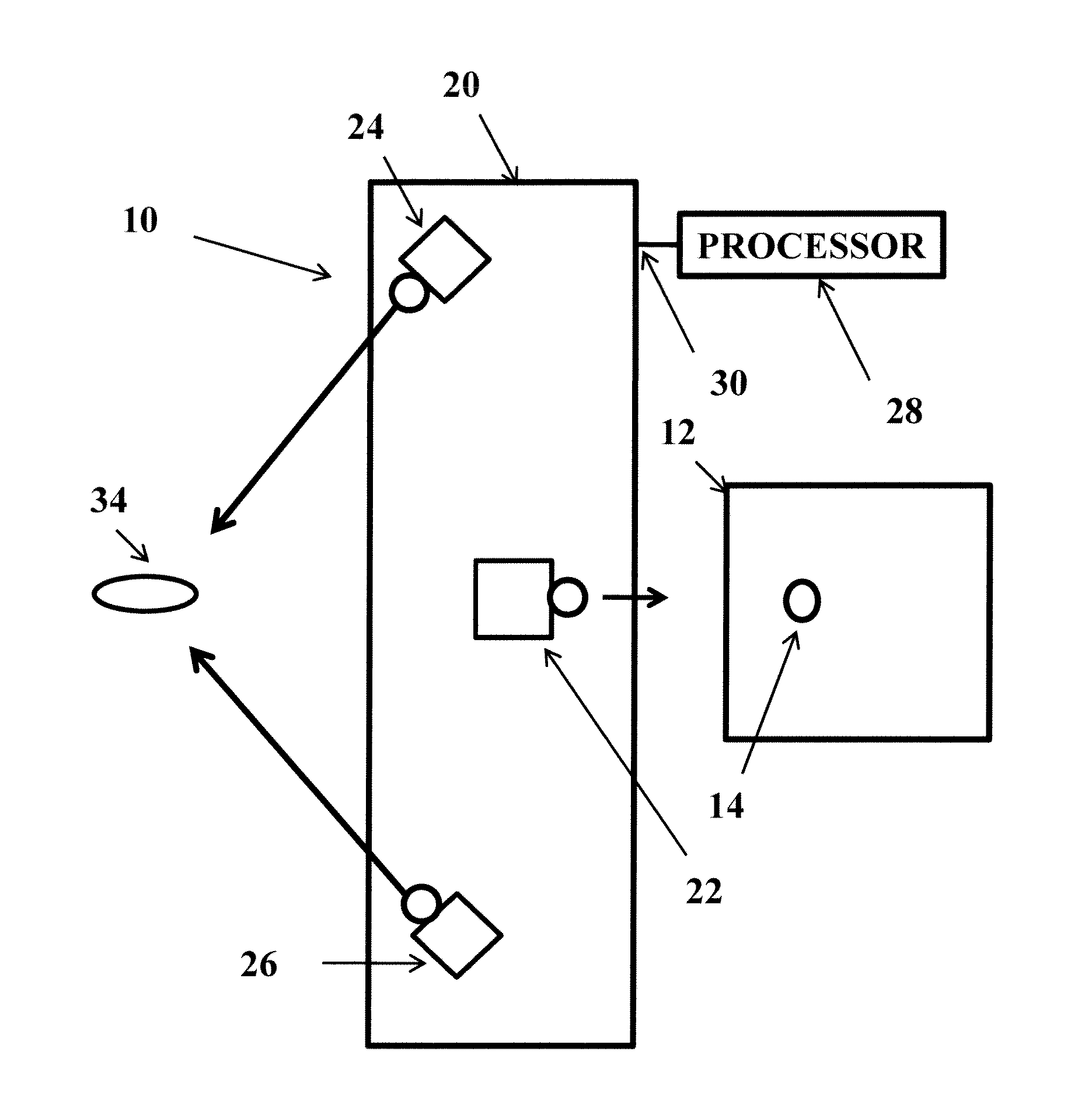
[0037]FIG. 1 illustrates a head worn, multi camera eye tracking system. A computer display 12 is provided. A calibration point 14 is provided at various locations on the display 12. A head worn, multi-camera device 20 can be a pair of glasses. The glasses 20 include an exo-camera 22, a first endo-camera 24 and a second endo-camera 26. Images from each of the cameras 22, 24 and 26 are provided to a processor 28 via output 30. The endo-cameras 24 and 26 are aimed at a user's eye 34. The endo camera 24 is aimed away from the user's eye 34. During calibration in accordance with an aspect of the present invention the endo-camera is aimed toward the display 12.

[0038]Next a method for geometric calibration of head-worn multi-camera eye tracking system as shown in FIG. 1 in accordance with an aspect of the present invention will be described

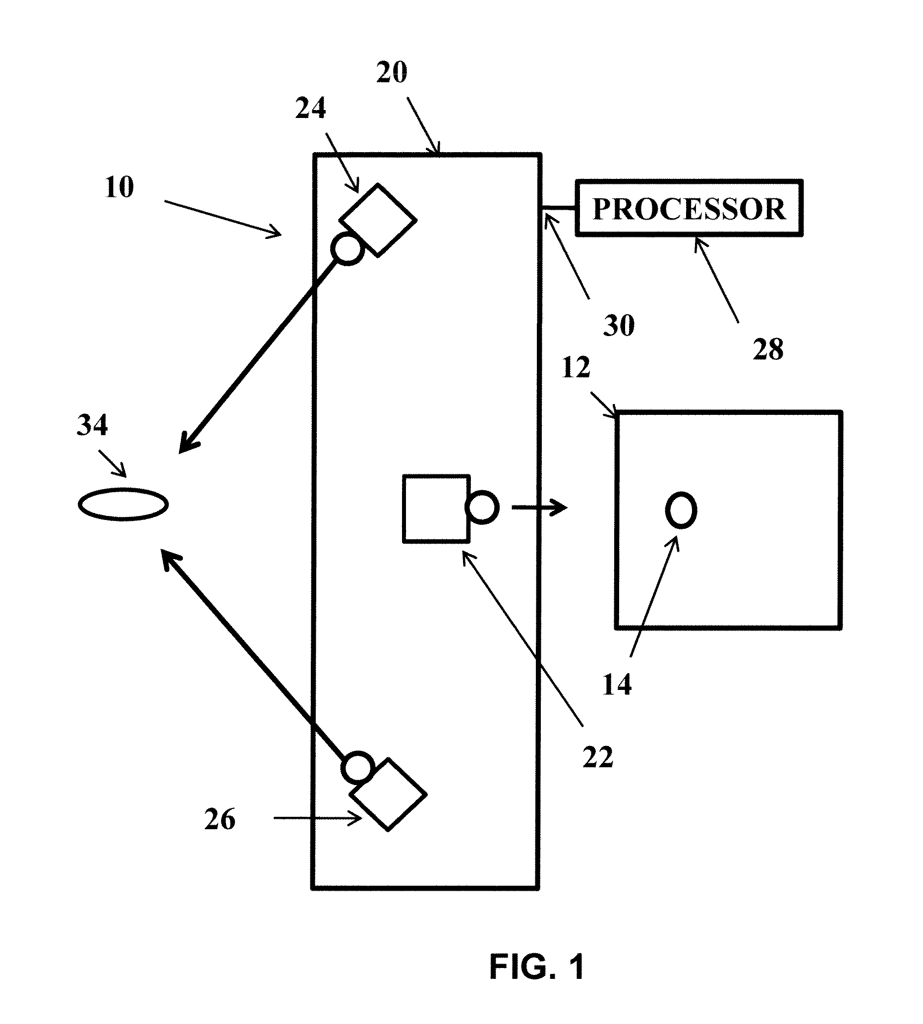
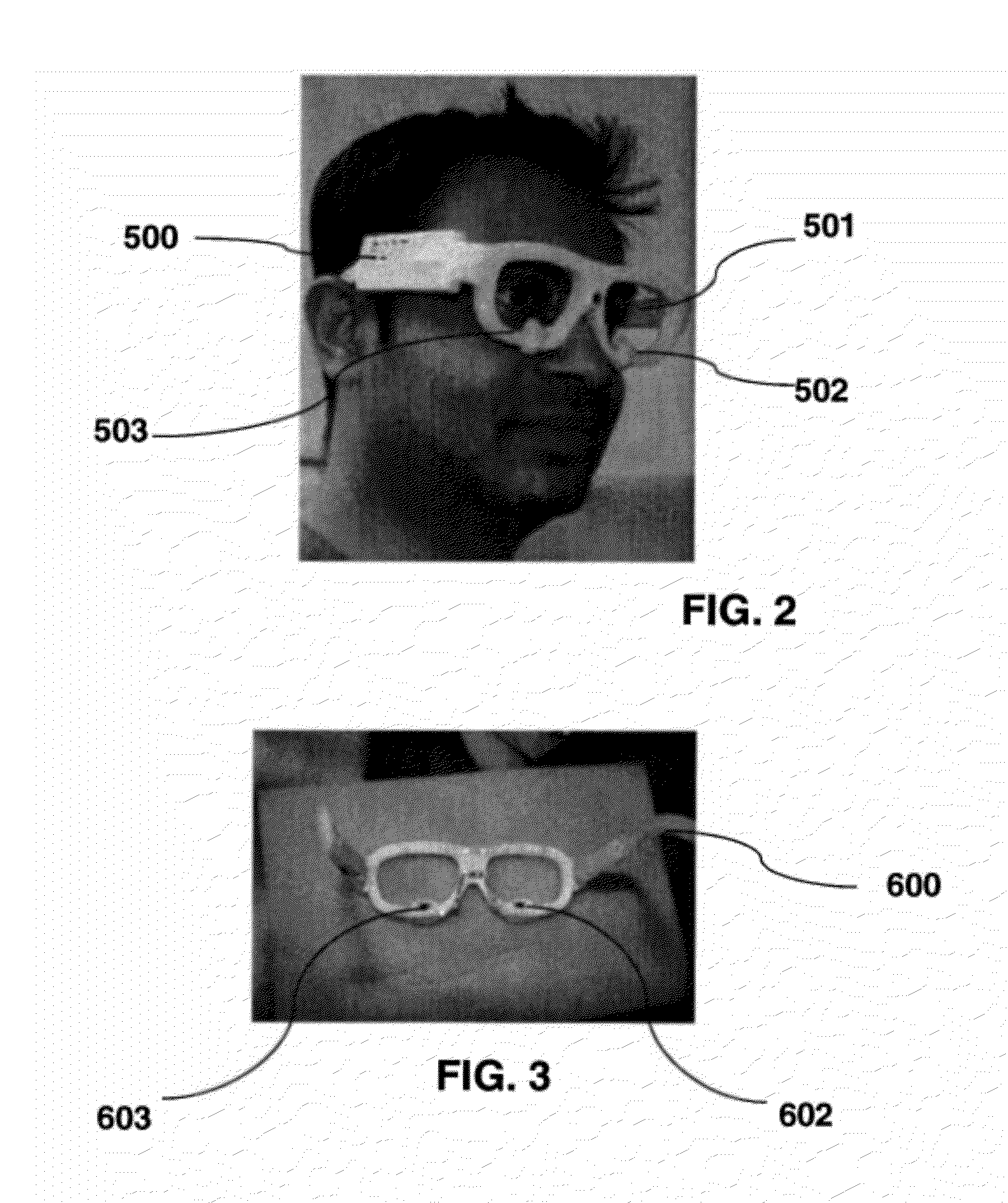
[0039]An embodiment of the glasses 20 is shown in FIGS. 2-4. A frame with endo and exo cameras is shown in FIG. 2. Such a frame is available from Eye-Co...


PUM


Abstract

A system and methods for geometric calibration and use of head-worn multi-camera eye tracking system are provided. The system calibrates the internal and external parameters of the cameras as well as the parameters of a compact geometric model of the human eye. An exo-camera determines a relative pose with regard to a computer monitor and endo-cameras determine the eyeball position and orientation. An endo-exo calibration and an endo-eye calibration each with an optimization step are included. A homography and a joint optimization step are also provided. A single point calibration re-establishes calibration. The system in operational mode determines a user's gaze direction to perform a computer input function.

Description

CROSS REFERENCE TO RELATED APPLICATIONS[0001]The present application claims the benefit of U.S. Provisional Patent Application Ser. No. 61 / 376,318 filed on Aug. 24, 2010, which is incorporated by reference herein in its entirety.BACKGROUND OF THE INVENTION[0002]The present invention relates to calibration of a user-wearable multi-camera system. More specifically, this invention relates to calibration that includes a pose of the multi-camera system with respect to the user.[0003]Augmented vision, also referred to as augmented reality or augmented reality vision, augments a user's view of the real world with superimposed computer generated graphical information. This information may be include, for example, a text label attached to some object in the scene, or a three-dimensional (3D) model of a patient's brain, derived from an MRI scan, and aligned to the real view of the person's head.[0004]The user may observe the real world directly with his or her eyes, and the additional graphic...

Claims


Application Information

Patent Timeline
IPC IPC(8): H04N13/02
CPCG02B27/017G02B2027/0138H04N13/0484H04N13/044G02B2027/014H04N13/344H04N13/383
Inventor ERNST, JANGENC, YAKUP
Owner SIEMENS MEDICAL SOLUTIONS USA INC
Why Eureka
Try Eureka