Scattering Tunable Display Using Reflective and Transmissive Modes of Illumination

a technology of transmitsive modes and tunable displays, applied in static indicating devices, optics, instruments, etc., can solve the problems of high cost of implementation, inability to use, and conventional backlight designs such as compact fluorescent lamps (cfl) can not be used, so as to achieve dramatic reduction of design and algorithm development, and the effect of keeping power consumption low

Inactive Publication Date: 2012-03-01
SHARP LAB OF AMERICA INC
View PDF4 Cites 13 Cited by
  • Summary
  • Abstract
  • Description
  • Claims
  • Application Information

AI Technical Summary

Benefits of technology

[0010]Disclosed herein is a display that can be operated in both reflection and transmission modes to meet everyday operational demands, while keeping power consumption low. The display is based upon a pixel micro-scattering mechanism. This mechanism permits the consistent operation of display pixels in both the reflection and transmission modes. The consistency of operational modes enables uniform display controls under either operational mode, dramatically reducing design and algorithm development.

Problems solved by technology

As the thickness of flat-panel liquid crystal (LC) displays is reduced to below 1 centimeter (cm), conventional backlight designs such as compact fluorescent lamp (CFL), which require that the light sources be distributed across the backlight panels, cannot be used due to the geometry limitations of these light sources.
But the cost of these implementations can be high since a large number of LEDs would be required.
However, the image quality of these edge-coupled displays cannot match that of displays using distributed LEDs as backlight light sources in the backlight panels.
In this kind of display implementation, the capability to address desired backlight light extraction cells is the key enabling technology, which is not easily achievable using edge-coupled LED backlight systems.
Regardless of whether an LED or CFL light source is used, LCD panel displays require a significant amount of power to operate, which is a disadvantage if the display is a portable battery-operated unit.
However, the operation of these types of displays completely depends on the availability of ambient light, dramatically limiting their application as a consumer product capable of operating in all kinds of environments, including dark or very dim ambient light conditions.

Method used


Image

  • Scattering Tunable Display Using Reflective and Transmissive Modes of Illumination
  • Scattering Tunable Display Using Reflective and Transmissive Modes of Illumination
  • Scattering Tunable Display Using Reflective and Transmissive Modes of Illumination

Examples


Embodiment Construction

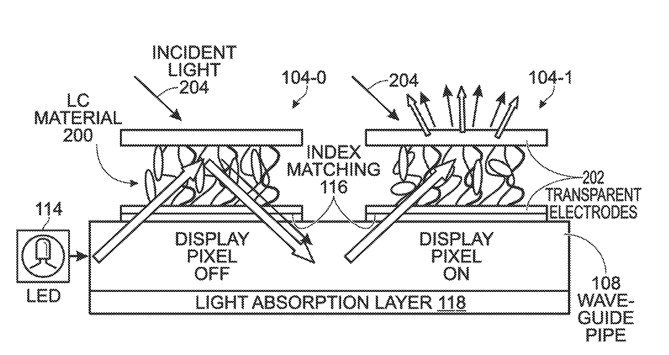
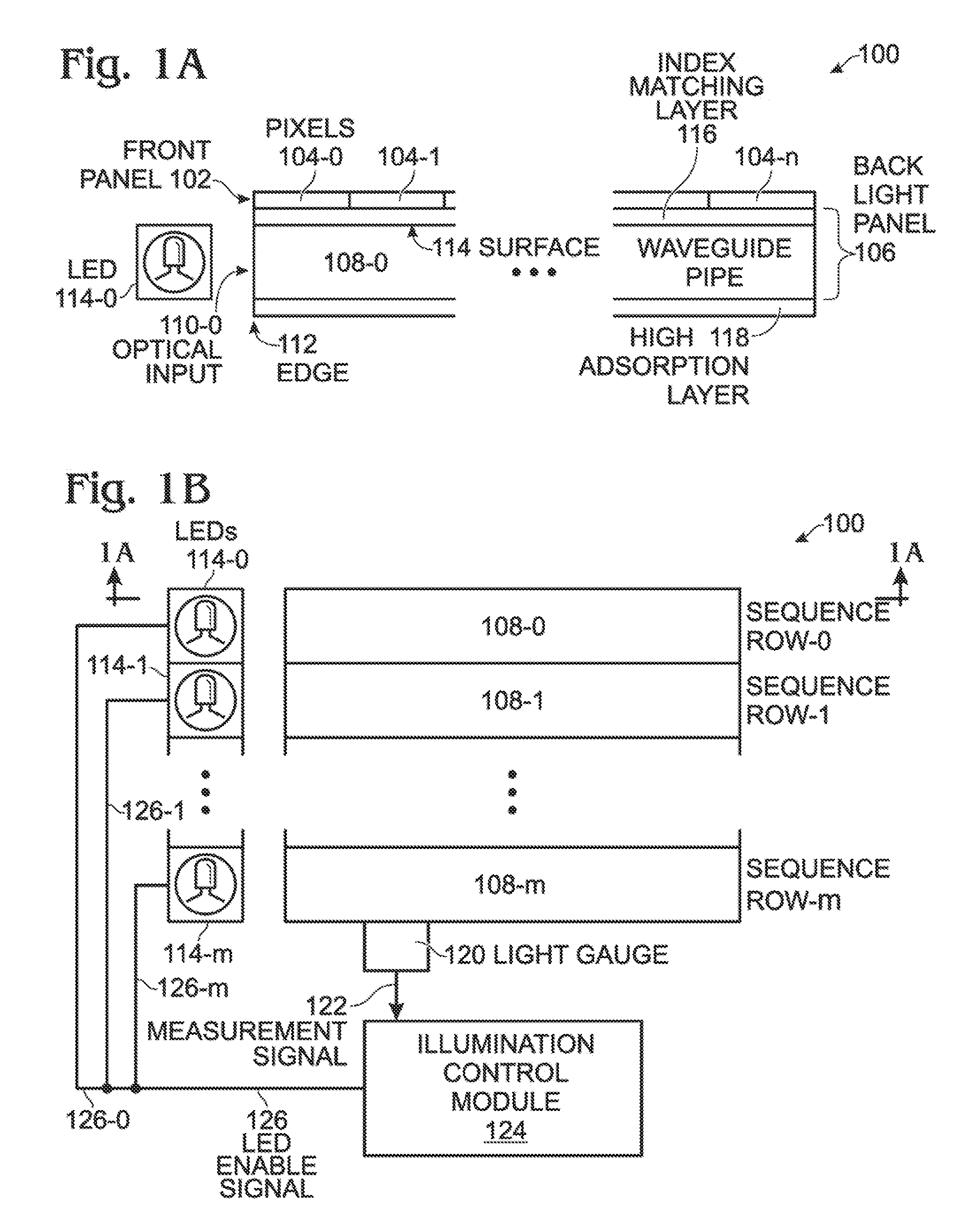
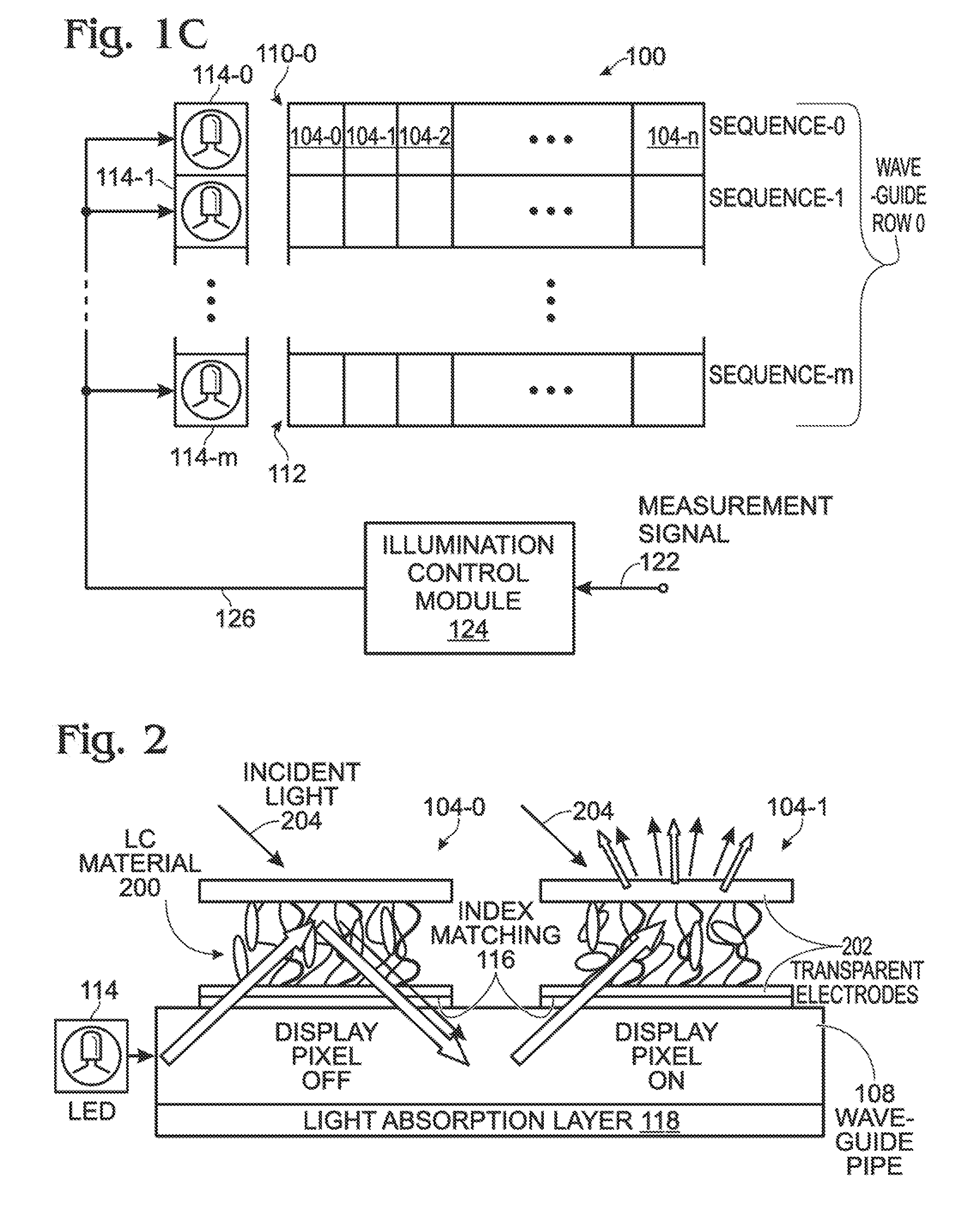
[0024]FIGS. 1A, 1B, and 1C are respectively, a partial cross-sectional view and two plan views of a scattering tunable display using reflection and edge-lit waveguide transmission modes of illumination. The display 100 comprises a front panel 102 with an array of selectable display pixels 104 arranged in a plurality of sequences. Shown are pixels 104-0 through 104-n in each sequence. Also shown are sequences 0 through m, where n and m are integer variables not limited to any particular value. A backlight panel 106 includes a plurality of edge-coupled waveguide pipes 108 formed in a plurality of rows. Shown are rows 0 through m (waveguide pipes 108-0 through 108-m), with each waveguide pipe row being associated with a display pixel sequence. In other aspects not shown, a waveguide row may be associated with a plurality of adjacent sequences. Each waveguide pipe 108 has an optical input 110 connected to an edge 112 and an optical output surface 114 underlying a corresponding display p...


PUM

PropertyMeasurementUnit
thicknessaaaaaaaaaa
timeaaaaaaaaaa
timeaaaaaaaaaa

Abstract

A scattering tunable display is provided that uses reflection and edge-lit waveguide transmission modes of illumination. A front panel is provided with an array of selectable display pixels arranged in a plurality of sequences. A backlight panel includes a plurality of edge-coupled waveguide pipes formed in a plurality of rows. Each waveguide pipe has an optical input connected to a corresponding light emitting diode (LED), and an optical output index-matched to a corresponding sequence of display pixels. A display pixel is enabled and ambient visible spectrum illumination is measured. In response to the measured ambient illumination being above a first minimum threshold, the display pixel is operated in a reflective illumination mode. In response to the measured ambient illumination being below the first minimum threshold, the display pixel is operated in a transmissive illumination mode.

Description

RELATED APPLICATION[0001]The application is a Continuation-in-Part of a pending application entitled, THREE-DIMENSIONAL DISPLAY USING ANGULAR PROJECTION BACKLIGHT, invented by Huang et al., Ser. No. 12 / 873,188, filed on Aug. 31, 2010, Attorney Docket No. SLA2739.BACKGROUND OF THE INVENTION[0002]1. Field of the Invention[0003]This invention generally relates to electronic displays and, more particularly, to a display capable of operation using both ambient and internally generated illumination sources.[0004]2. Description of the Related Art[0005]As the thickness of flat-panel liquid crystal (LC) displays is reduced to below 1 centimeter (cm), conventional backlight designs such as compact fluorescent lamp (CFL), which require that the light sources be distributed across the backlight panels, cannot be used due to the geometry limitations of these light sources. Ultra-thin display designs might be implemented using LEDs with small-volume packages. But the cost of these implementations...

Claims


Application Information

Patent Timeline
Patent Type & Authority Applications(United States)
IPC IPC(8): G02F1/1335
CPCG09G2300/0456G09G3/36G09G2300/046G02F2001/133626G02F1/1334G02F2201/58G09G3/3473G02F1/133555G02F1/133615G09G2360/144G02F1/133626
Inventor HUANG, JIANDONGVOUTSAS, APOSTOLOS T.
Owner SHARP LAB OF AMERICA INC
Why Eureka
Try Eureka