Image forming apparatus

a technology of forming apparatus and forming tube, which is applied in the direction of electrographic process apparatus, instruments, optics, etc., can solve the problems of premature burnout of filament, blackening of glass tubes, and adverse effects, and achieve the effect of restricting the occurrence of defective overshoot and preventing the shortened life of halogen lamps

Active Publication Date: 2012-03-01
RICOH KK
View PDF3 Cites 91 Cited by
  • Summary
  • Abstract
  • Description
  • Claims
  • Application Information

AI Technical Summary

Benefits of technology

[0013]The present invention aims to solve the aforementioned problems of a conventional fixing device using a halogen lamp as a heat source and provi

Problems solved by technology

In such a case, the temperature of the filament and the density of the gas inside the halogen heaters can become uneven, with the result that the halogen cycle may take place normally at one place but not at another, which may cause adverse effects such as blackening of the glass tube or premature burnout of the filament.
Even though the tungsten is lost from the filament, the tungsten halide cannot be thermally decomposed due to a low filament temperature.
As a result, chemical attack occurs in the edge portions a

Method used


Image

  • Image forming apparatus
  • Image forming apparatus
  • Image forming apparatus

Examples


first embodiment

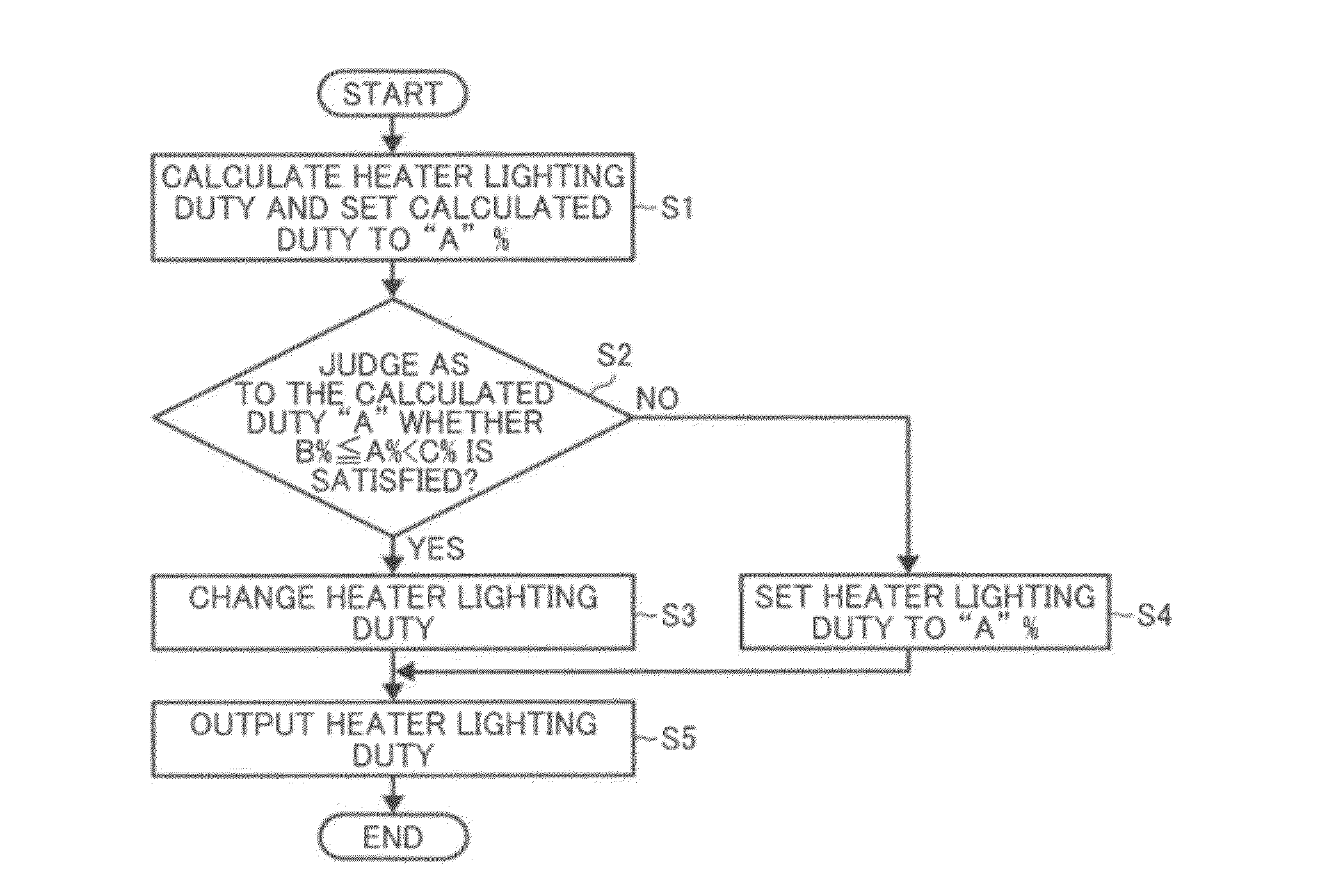
[0039]FIG. 4 is a flowchart illustrating controlling the halogen heater. As illustrated in FIG. 4, first, a heater lighting duty or ON duty is calculated from the history of the temperatures of the fixing roller detected by the temperature sensor 60 (S1). The calculated ON duty here is set to “A” %. Next, it is judged whether the calculated duty “A” satisfies a relation B %≦A %≦C % (S2). If, in S2, the duty “A” satisfies the relation B %≦A %≦C %, the process proceeds to S3 in which the heater ON duty is changed, and the heater ON duty is output so that the heater lighting control is performed in S5. By contrast, if, in S2, it is judged that the calculated duty “A” does not satisfy the relation B %≦A %≦C %, that is, the calculated duty “A” is judged to be less than “B” or more than “C”, the process proceeds to S4 and the duty “A” is set and the heater lighting control is performed in S5.

[0040]The duties B and C are set as described below so that, when the calculated ON duty “A” % is ...

second embodiment

[0041]FIG. 5 is a flowchart illustrating controlling the halogen heater. First, a heater ON duty “A” is calculated from the history of the temperatures of the fixing roller detected by the temperature sensor 60 using PID control (S11). Next, it is determined whether the calculated duty “A” satisfies the relation B %≦A %≦C % (S12). If, in S12, the duty “A” satisfies the relation B %≦A %≦C %, the process proceeds to S13 in which the heater ON duty is set to 0 (zero) %. Specifically, the heater is not lighted. By contrast, if it is judged that the duty “A” is less than “B” or more than “C” in S12, the process proceeds to S14 in which the heater ON duty is set to “A” to be processed to output the heater ON duty in S15, thereby performing the heater lighting control.

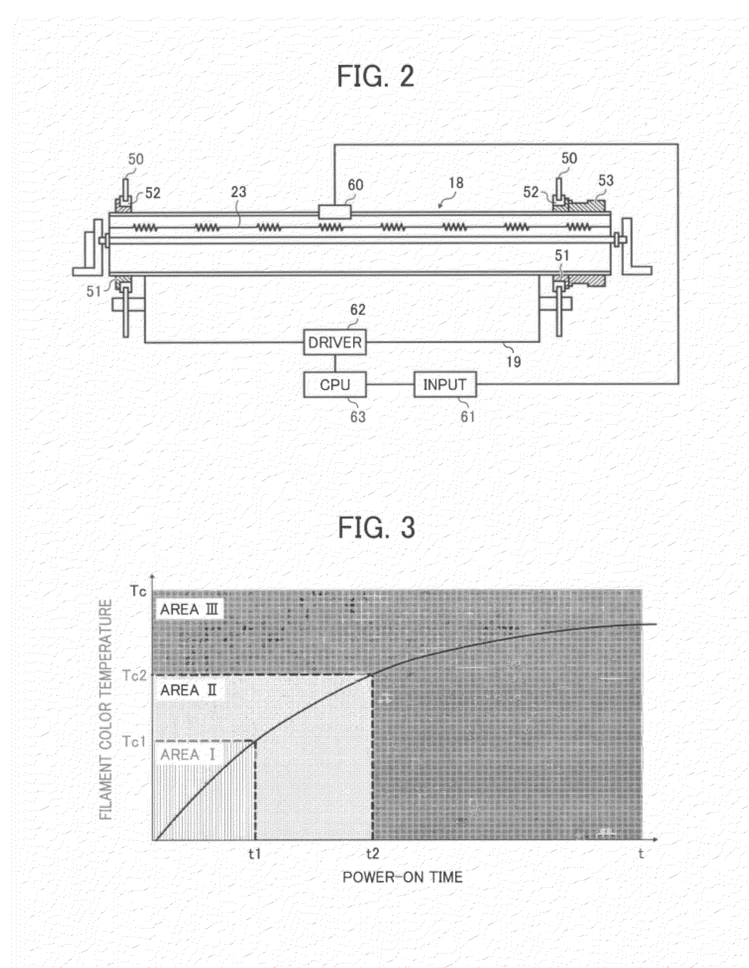
[0042]The duties B and C are set as described below so that, when the calculated ON duty “A” % is included in Area II in FIG. 3, i.e., the area in which chemical attack tends to occur, the heater is not turned on in the secon...

third embodiment

[0044]The duties B and C are set as described below so that, when the calculated ON duty “A” % is included in Area II, i.e., the area in which chemical attack tends to occur, the ON duty is changed to the maximum ON duty so that the halogen cycle does not occur in the third embodiment, whereby the abnormal halogen cycle is securely eliminated to prevent the lifetime of the heater from decreasing and the temperature decrease due to the power-off of the halogen lamp can be prevented.

[0045]FIG. 7 is a flowchart illustrating a fourth embodiment of controlling the halogen heater. In the fourth embodiment, first, a heater ON duty “A” is calculated from the history of the temperatures of the fixing roller detected by the temperature sensor 60 using PID control (S31). Next, it is judged whether the calculated duty “A” satisfies the relation B %≦A %≦C % (S32). In S32, if the duty “A” is equal to or more than “B” and less than “C”, the process proceeds to S33 and the heater ON duty is set to ...


PUM


Abstract

An image forming apparatus includes a fixing device including a fixing member; a pressure member to press against the fixing member; and a halogen lamp to heat the fixing member, and a controller to control the halogen lamp. The controller controls an ON duty of the halogen lamp according to a control cycle, and sets the ON duty including two thresholds consisting of a first ON duty and a second ON duty that is larger than the first ON duty. The controller calculates an ON duty of the halogen lamp, judges whether the calculated ON duty is equal to or more than the first duty and less then the second duty, and changes the calculated ON duty when the calculated ON duty is equal to or more than the first duty and less then the second duty.

Description

CROSS-REFERENCE TO RELATED APPLICATIONS[0001]The present application claims priority from Japanese patent application number 2010-193862, filed on Aug. 31, 2010, the entire contents of which are incorporated by reference herein.FIELD OF THE INVENTION[0002]The present invention relates to an image forming apparatus including a fixing device with a built-in halogen heater.DESCRIPTION OF THE RELATED ART[0003]Generally, image forming apparatuses such as electrophotographic printer, copier or the like include a fixing device having a fixing member, such as a fixing roller, to fix with heat and pressure an unfixed toner image onto a recording medium such as a sheet of paper have conventionally been widely known. Such a fixing member is heated by a heat source such as a halogen heater. A pressure member, such as a pressure roller, is provided opposite the fixing member to press against the fixing member. The sheet carrying the unfixed toner image thereon passes through a nip formed between...

Claims


Application Information

Patent Timeline
IPC IPC(8): G03G15/20
CPCG03G15/2039
Inventor IKEBUCHI, YUTAKAYAMAGUCHI, YOSHIKISHIMOKAWA, TOSHIHIKOISHII, KENJIIWAYA, NAOKIIMADA, TAKAHIROTOKUDA, TETSUOHASE, TAKAMASAYOSHINAGA, HIROSHIFUJIMOTO, IPPEIYOSHIKAWA, MASAAKI
Owner RICOH KK
Why Eureka
Try Eureka