Printer heating element

a technology of heating element and fuser, which is applied in the field of fuser, can solve the problems of image quality problems and reduce the heater temperature, and achieve the effect of reducing the complexity of the fuser heater design and lowering the unit manufacturing cos

Inactive Publication Date: 2012-03-01
XEROX CORP
View PDF2 Cites 15 Cited by
  • Summary
  • Abstract
  • Description
  • Claims
  • Application Information

AI Technical Summary

Benefits of technology

[0009]Accordingly, the encompassed heater designs show two options, both of which require only one TCO to support monitoring requirements for abnormal temperatures. An improved fuser is disclosed that includes a heater which provides uniformity at the surface of the fuser that contacts an imaged sheet by configuring the heater to include a single resistive element shaped to heat multiple sheet sizes with independently controllable conductive traces connected to outer segments of the resistive element and adapted to supply electricity to separate sections of the resistive element in accordance with the size of sheet being fed through the fuser and without cold spot compensation. With this heater configuration only one thermal cut-off for safety purposes is required, thereby lowering the unit manufacturing cost and reducing the complexity of the fuser heater design.

Problems solved by technology

Multi-tap series controlled ceramic heaters of this design have a flaw in that a conductor interface to the heat-producing materials creates a cold spot which reduces the heater temperature locally and creates a radial cold area in the fuser roll causing image quality issues.

Method used


Image

  • Printer heating element
  • Printer heating element
  • Printer heating element

Examples


Embodiment Construction

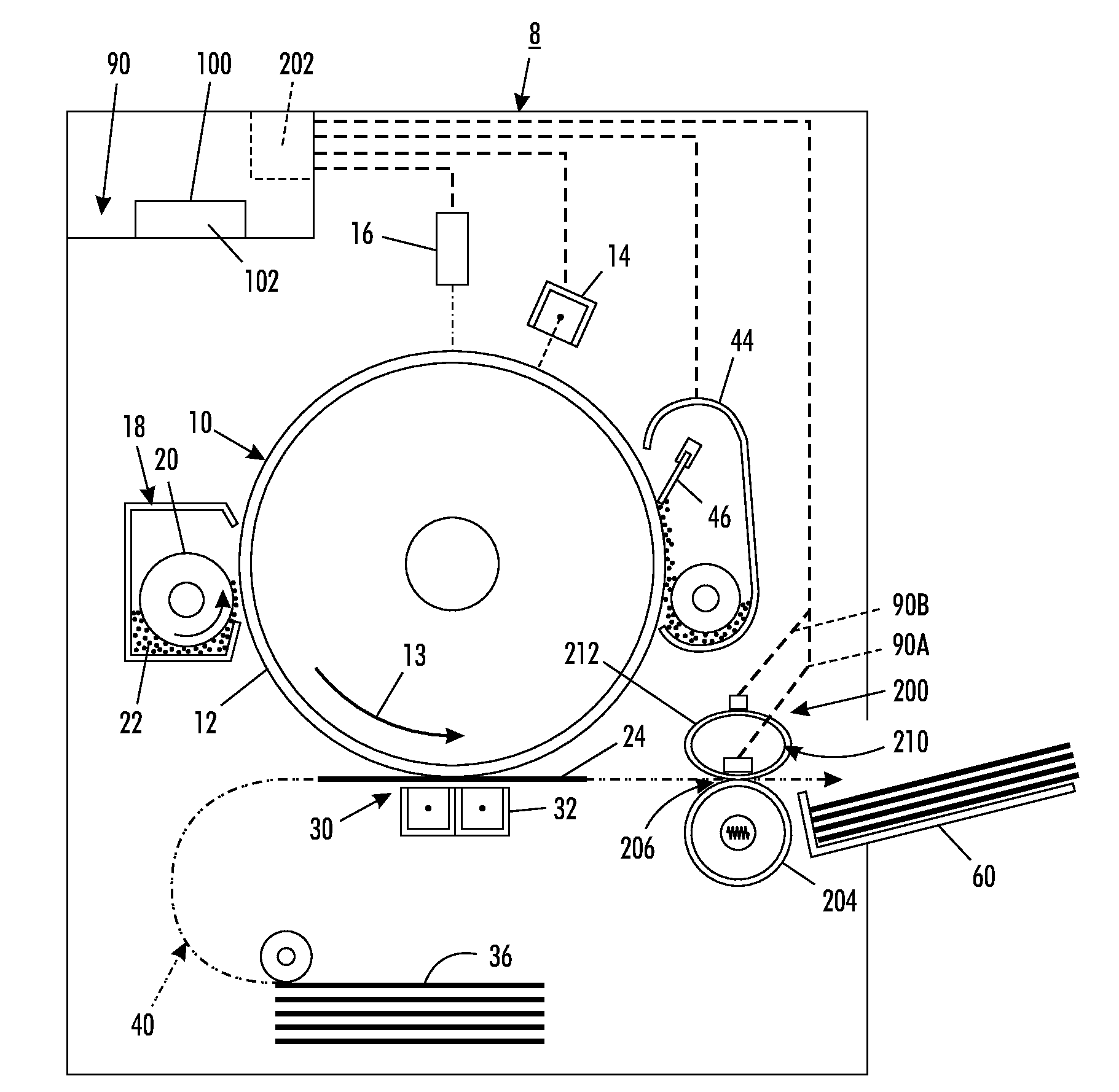
[0018]Referring now to FIG. 1, an electrostatographic or toner-imaging machine 8 is shown. As is well known, a charge receptor or photoreceptor 10 having an imageable surface 12 and rotatable in a direction 13 is uniformly charged by a charging device 14 and imagewise exposed by an exposure device 16 to form an electrostatic latent image on the surface 12. The latent image is thereafter developed by a development apparatus 18 that, for example, includes a developer roll 20 for applying a supply of charged toner particles 22 to such latent image. The developer roll 20 may be of any of various designs, such as, a magnetic brush roll or donor roll, as is familiar in the art. The charged toner particles 22 adhere to appropriately charged areas of the latent image. The surface of the photoreceptor 10 then moves, as shown by the arrow 13, to a transfer zone generally indicated as 30. Simultaneously, a print sheet 24 on which a desired image is to be printed is drawn from sheet supply stac...


PUM


Abstract

An improved fuser includes a heater which provides uniformity at the surface of a fuser roll that contacts an imaged sheet. The heater is configured to include a single resistive element shaped to heat multiple sheet sizes with independently controllable conductive traces connected to outer segments of the resistive element and adapted to supply electricity to separate sections of the resistive element in accordance with the size of sheet being fed through the fuser center registered and without the need for cold spot compensation.

Description

BACKGROUND[0001]1. Field of the Disclosure[0002]This invention relates generally to electrostatographic reproduction machines, and more particularly, to a fuser adapted to handle multiple paper widths and is especially useful in center registered machines.[0003]2. Description of Related Art[0004]In electrostatographic printing, commonly known as xerographic or printing or copying, an important process step is known as “fusing”. In the fusing step of the xerographic process, dry marking making material, such as toner, which has been placed in imagewise fashion on an imaging substrate, such as a sheet of paper, is subjected to heat and / or pressure in order to melt the otherwise fuse the toner permanently on the substrate. In this way, durable, non-smudging images are rendered on the substrates.[0005]The most common design of a fusing apparatus as used in commercial printers includes two rolls, typically called a fuser roll and a pressure roll, forming a nip therebetween for the passag...

Claims


Application Information

Patent Timeline
Patent Type & Authority Applications(United States)
IPC IPC(8): G03G15/20
CPCG03G15/2053
Inventor TRESS, TAB A.PAWLIK, ROBERT S.GILLIS, BRIANSMITH, NATHAN E.
Owner XEROX CORP
Why Eureka
Try Eureka