
Heart rate measuring device

a technology of heart rate and measuring device, which is applied in the field of heart rate measurement, can solve the problems of high cost of implementation, poor safety, and poor skin quality of children, and achieve the effect of low cos

Active Publication Date: 2012-03-01
KONINKLIJKE PHILIPS ELECTRONICS NV
View PDF7 Cites 6 Cited by
  • Summary
  • Abstract
  • Description
  • Claims
  • Application Information

AI Technical Summary

Benefits of technology

[0008]It is the object of the invention to provide a possibility to measure the heart rate and / or the heart rate variation of a subject in a reliable and non-obtrusive way while keeping the implementation costs low.
[0014]Measuring a signal generated by a movement of the subject with a horizontal component is advantageous since—for a lying person—the force due to the aortic arch impulse is typically oriented in the horizontal direction relative to the ground and relative to the longitudinal axis of the holder, respectively.
[0023]Preferably, a capacitive measuring system is used due to its reliability and low implementation costs. Preferably, the capacitive measuring system is intended to measure human heart activity, in particular heart activity of neonates lying in an incubator. The capacitive measuring system is easily combinable with a scale adapted for determining a baby's or neonate's weight.
[0024]The inventive heart rate measuring apparatus can easily built in or be embedded in an incubator, such as a neonatal intensive care incubator. Measuring the HR without using sensors attached to or positioned close to the subject's body is preferred. It goes without saying that this is less obtrusive, in particular for neonates which lie in a neonatal intensive care incubator.

Problems solved by technology

However, the use of the ballistographic method is problematic due to the fact that such a method mainly measures forces oriented in a vertical direction relative to the ground.
It goes without saying that the skin of the child is very thin and fragile, and may be damaged by removing the electrodes.

Method used


Image

  • Heart rate measuring device
  • Heart rate measuring device

Examples


Embodiment Construction

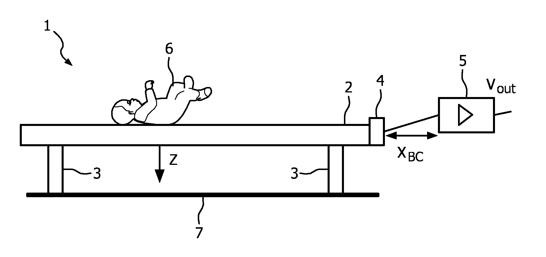
[0030]It is a general idea of the invention to use a motion sensor adapted for measuring a movement in a horizontal direction rather than in the vertical direction relative to the ground. This makes no modification of the holder necessary and the force due to the aortic arch impulse is mainly oriented in the horizontal direction while in a direction perpendicular to the horizontal direction, i.e. in the vertical direction relative to the ground, the forces are much smaller.

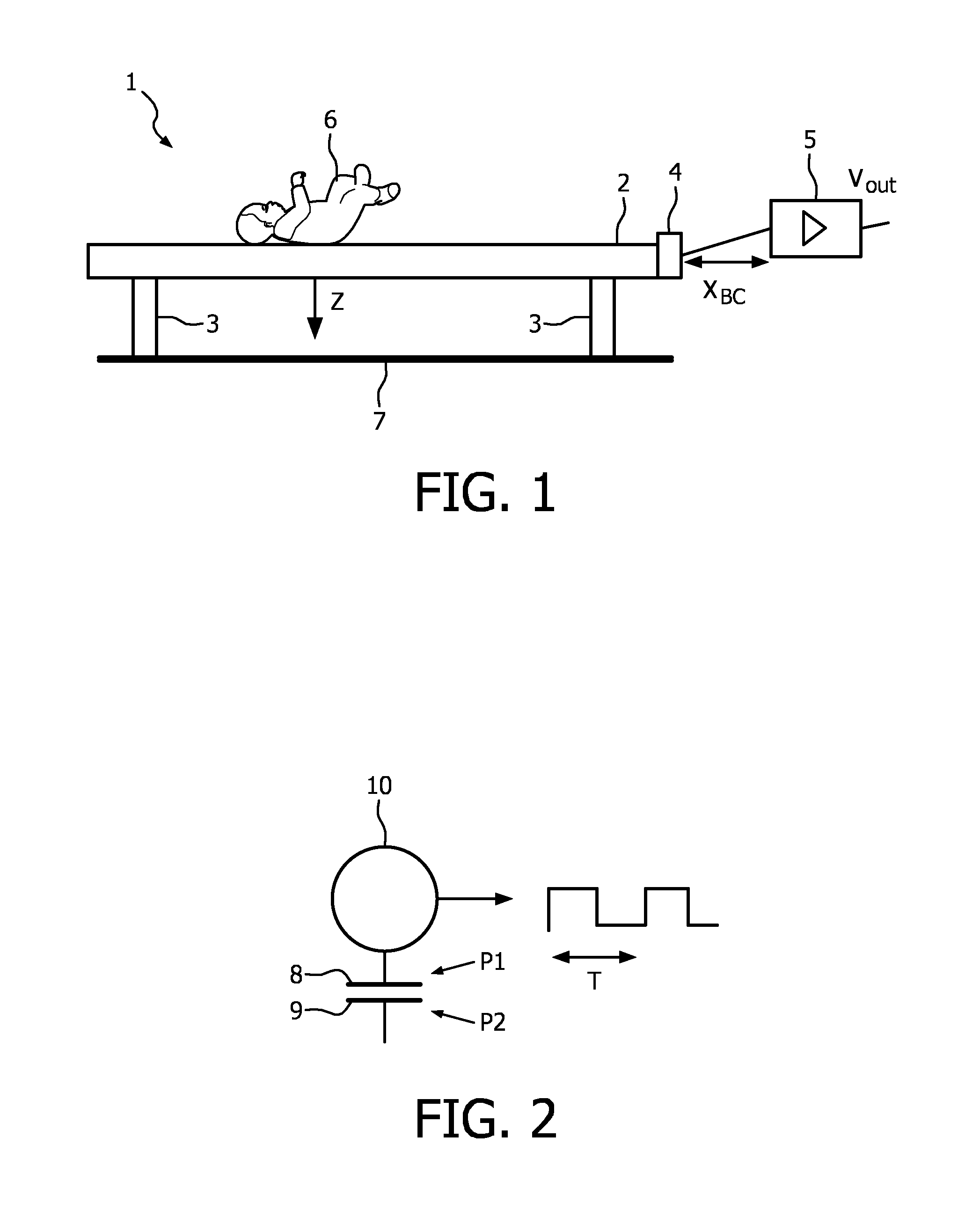
[0031]FIG. 1 schematically shows a baby or neonate 6 lying on a holder 2 operatively connected to a motion sensor 4, wherein the ground 7 is the “fixed world”, also referred to as fixed ground. The heart rate measuring apparatus 1 comprises the motion sensor 4 corresponding to an electrical motion sensor according to a preferred embodiment of the invention. The motion sensor 4 comprises a capacitive measuring system which is applied according to the preferred embodiment of the invention. The holder 2 is adapted fo...


PUM


Abstract

The invention relates to a heart rate measuring apparatus and a method, adapted for measuring a subject's (6) heart rate and / or heart rate variation. The heart rate measuring apparatus (1) comprises a holder (2) adapted for carrying a portion of a body part of the subject (6) lying on or resting against the holder (2), a motion sensor (4) operatively connected to the holder (2), wherein the holder (2) is adapted for being at least partly moveable in a horizontal direction relative to the ground (7), the motion sensor (4) being adapted for measuring a signal generated by a movement of the subject (6) at least partly in the horizontal direction. In this way, a reliable signal is obtained adapted for measuring the heart rate and / or heart rate variation of a subject while keeping the implementation costs low.

Description

FIELD OF THE INVENTION[0001]The invention relates to the field of heart rate measuring, and especially to measuring the heart rate and / or the heart rate variability in an unobtrusive way.BACKGROUND OF THE INVENTION[0002]Document US 2008 / 0077020 A1 describes a method and an apparatus for monitoring vital signs, such as cardiopulmonary activity, using a ballistograph. The method and the apparatus are used to monitor an infant sleeping in a crib, a patient in a hospital, a person with a chronic disease at home or in professional care, or a person in an elder-care setting.[0003]Heart activity is one of the most important vital life signs for a human or an animal. In the following, a subject comprises a human, such as a baby or a neonate, and an animal. In this description, neonates are focused on. However, the idea of the invention is applicable to all humans or animals. The heart rate, HR for short, and also the heart rate variation or heart rate variability, HRV for short, have become...

Claims


Application Information

Patent Timeline
IPC IPC(8): A61B5/02
CPCA61B5/1102A61B2503/04A61B5/6891
Inventor AARTS, RONALDUS MARIABAMBANG OETOMO, SIDARTO
Owner KONINKLIJKE PHILIPS ELECTRONICS NV
Learn More