
Method and system for sensing external magnetic fields using a multi-function coil of an implantable medical device

a multi-function coil and magnetic field technology, applied in the field of implantable medical devices, can solve the problems of imds being unable to reliably operate in a physiologic preferred manner in certain modes, field interference with imd operation, and cardiac signal over- or under-sensing,

Inactive Publication Date: 2012-03-01
PACESETTER INC
View PDF2 Cites 15 Cited by
  • Summary
  • Abstract
  • Description
  • Claims
  • Application Information

AI Technical Summary

Benefits of technology

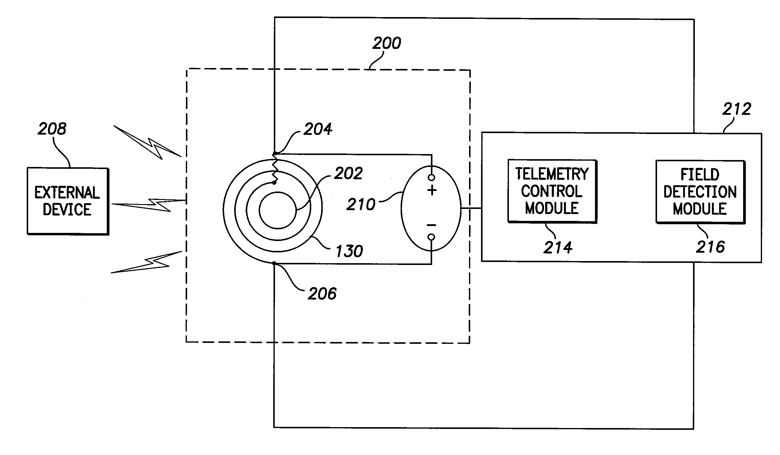
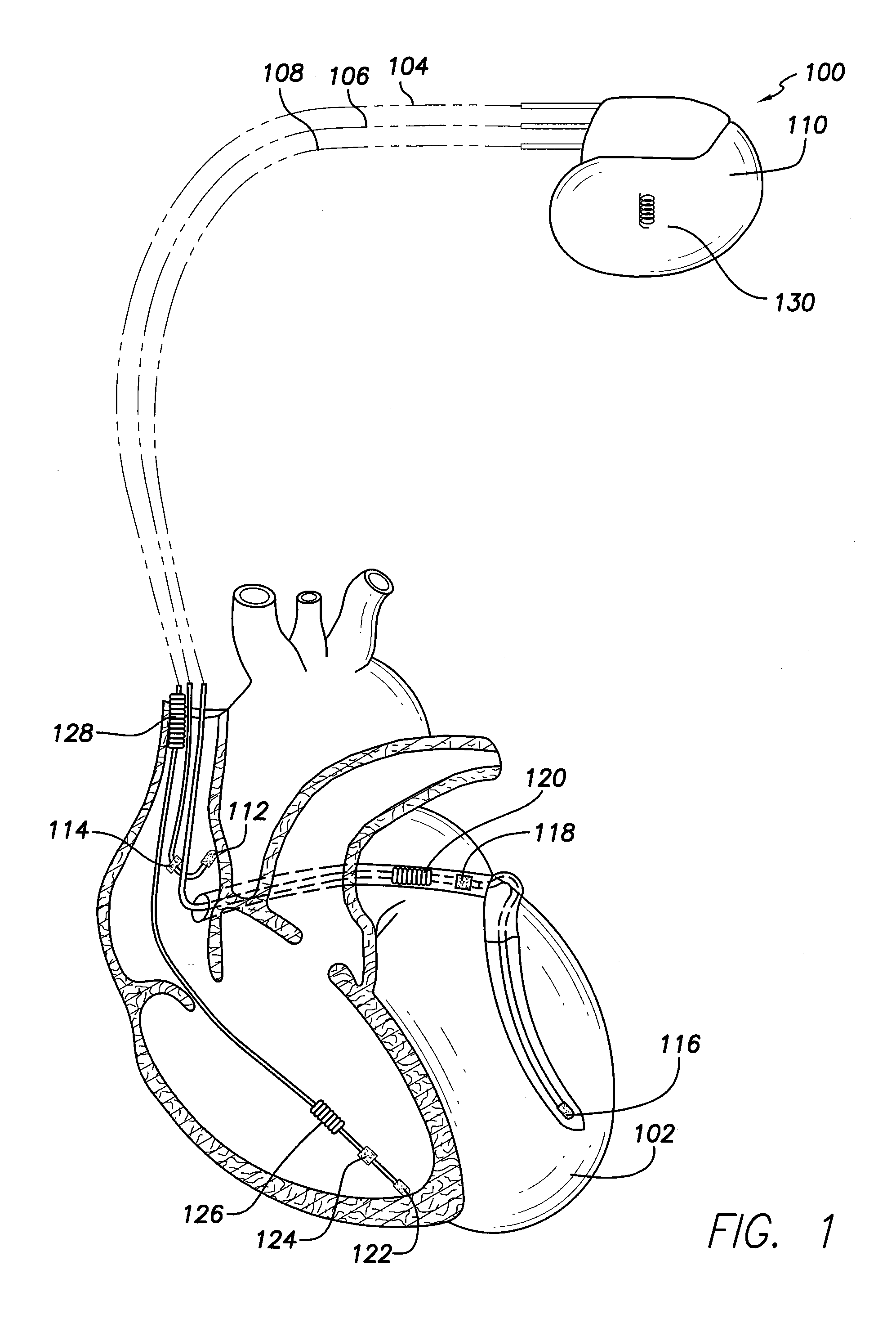
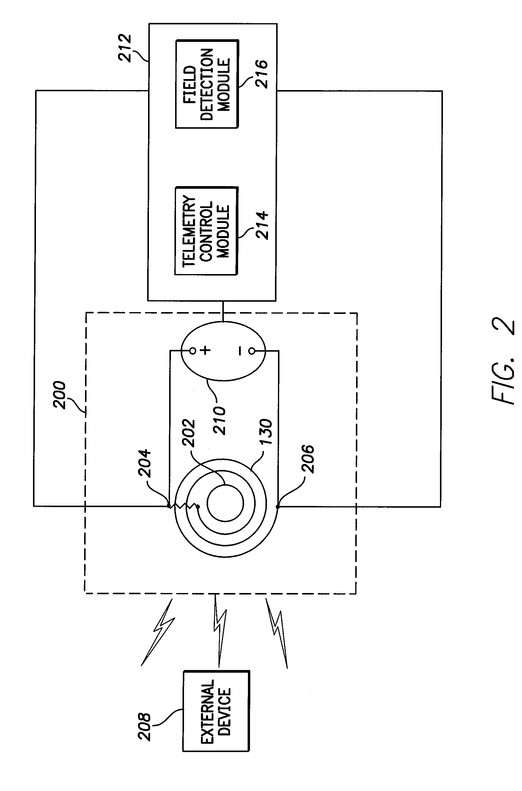
[0007]In one embodiment, an implantable medical device (IMD) includes a lead, a monitoring module, a multi-function conductive (MFC) coil, and a field detection module. The monitoring module identifies cardiac events based on the cardiac signals and directs stimulus pulses to be delivered to the heart through one or more electrodes connected to the lead. The MFC coil has an electric characteristic that varies based on exposure of the coil to an external magnetic field. The field detection module detects exposure of the coil to the external magnetic field by applying a field detection signal to the coil and identifying a change in the electric characteristic of the MFC coil. The field detection module switches operation of the monitoring module to an MR safe mode based on the change that is identified

Problems solved by technology

When IMDs are exposed to external magnetic fields such as those of MR imaging systems, the fields may interfere with operation of the IMD.
The electric charges can cause over- or under-sensing of cardiac signals in the electrodes and leads.
However, when IMDs are exposed to higher magnetic fields, the IMDs may be unable to reliably operate in a physiologic preferred manner in certain modes.
These extra sensors that are added to the IMDs consume the limited volume inside the IMD housing.
The GMR sensors consume space in the IMD that may be used for other components.
Additionally, the GMR sensors may be limited in that the sensors may be capable of only detecting exposure of the IMDs to relatively weak external magnetic fields.
The sensors may be unable to differentiate between different external magnetic fields.
For example, the sensors may be unable to distinguish between an external magnetic field generated by a relatively weak magnet and an external magnetic field generated by an MR imaging system.

Method used


Image

  • Method and system for sensing external magnetic fields using a multi-function coil of an implantable medical device
  • Method and system for sensing external magnetic fields using a multi-function coil of an implantable medical device
  • Method and system for sensing external magnetic fields using a multi-function coil of an implantable medical device

Examples


Embodiment Construction

[0021]In the following detailed description, reference is made to the accompanying drawings which form a part hereof, and in which are shown by way of illustration specific embodiments in which the present invention may be practiced. These embodiments, which are also referred to herein as “examples,” are described in sufficient detail to enable those skilled in the art to practice the invention. It is to be understood that the embodiments may be combined or that other embodiments may be utilized, and that structural, logical, and electrical variations may be made without departing from the scope of the present invention. The following detailed description is, therefore, not to be taken in a limiting sense, and the scope of the present invention is defined by the appended claims and their equivalents. In this document, the terms “a” or “an” are used, as is common in patent documents, to include one or more than one. In this document, the term “or” is used to refer to a nonexclusive o...


PUM


Abstract

An implantable medical device includes a lead, a monitoring module, a multi-function conductive (MFC) coil, and a field detection module. The monitoring module identifies cardiac events based on the cardiac signals and directs stimulus pulses to be delivered to the heart through one or more electrodes connected to the lead. The MFC coil has an electric characteristic that varies based on exposure of the coil to an external magnetic field. The field detection module detects exposure of the coil to the external magnetic field by applying a field detection signal to the coil and identifying a change in the electric characteristic of the MFC coil. The field detection module switches operation of the monitoring module to an MR safe mode based on the change that is identified.

Description

FIELD OF THE INVENTION[0001]The present invention generally pertains to implantable medical devices and more particularly to methods and systems that switch modes of operation of an implantable medical device based on the presence of an external magnetic field.BACKGROUND OF THE INVENTION[0002]An implantable medical device (IMD) is implanted in a patient to monitor, among other things, electrical activity of a heart and to deliver appropriate electrical therapy, as required. Implantable medical devices include pacemakers, cardioverters, defibrillators, implantable cardioverter defibrillators (ICD), and the like. The electrical therapy produced by an IMD may include pacing pulses, cardioverting pulses, and / or defibrillator pulses to reverse arrhythmias (e.g., tachycardias and bradycardias) or to stimulate the contraction of cardiac tissue (e.g., cardiac pacing) to return the heart to its normal sinus rhythm.[0003]Strong magnetic fields may be produced by magnetic resonance (MR) imagin...

Claims


Application Information

Patent Timeline
Patent Type & Authority Applications(United States)
IPC IPC(8): A61N1/08
CPCA61N1/056A61N2001/086A61N1/08A61N1/3688A61N1/3718A61N1/086
Inventor DIANATY, ALISHEHADA, RAMEZ
Owner PACESETTER INC
Learn More