Circuit board and circuit module

a circuit board and circuit module technology, applied in the field of circuit boards and circuit modules, can solve the problems of difficult to provide impedance matching between the semiconductor and the likely to deterioration of the impedance matching, and achieve the effect of more accurate impedance matching

Active Publication Date: 2012-03-08
MURATA MFG CO LTD
View PDF9 Cites 19 Cited by
  • Summary
  • Abstract
  • Description
  • Claims
  • Application Information

AI Technical Summary

Benefits of technology

[0011]According to various preferred embodiments of the present invention, impedance matching can more accu...

Problems solved by technology

Meanwhile, as described below, the flexible sheet 500 has a problem in that it is difficult to provide impedance matching between the semiconductor element 602 and the ...

Method used


Image

  • Circuit board and circuit module
  • Circuit board and circuit module
  • Circuit board and circuit module

Examples


Embodiment Construction

[0020]Hereinafter, a circuit board and a circuit module according to preferred embodiments of the present invention will be described with reference to the drawings.

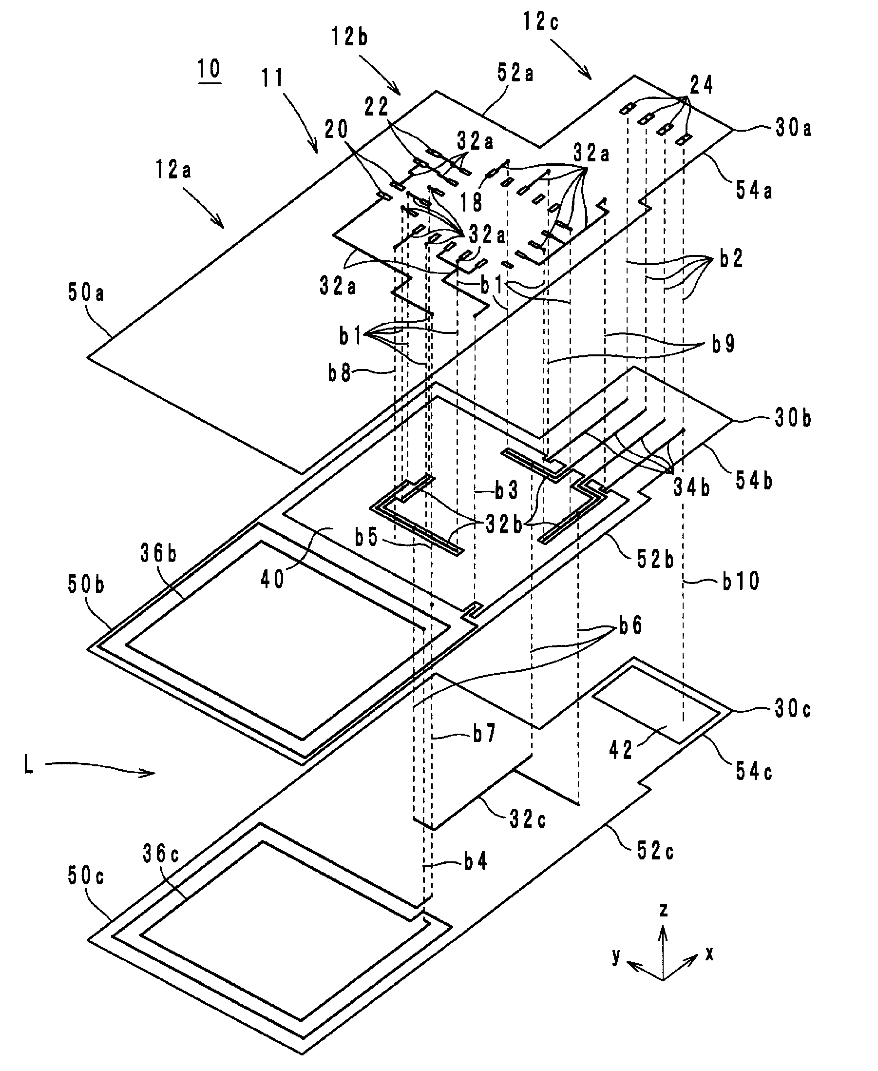
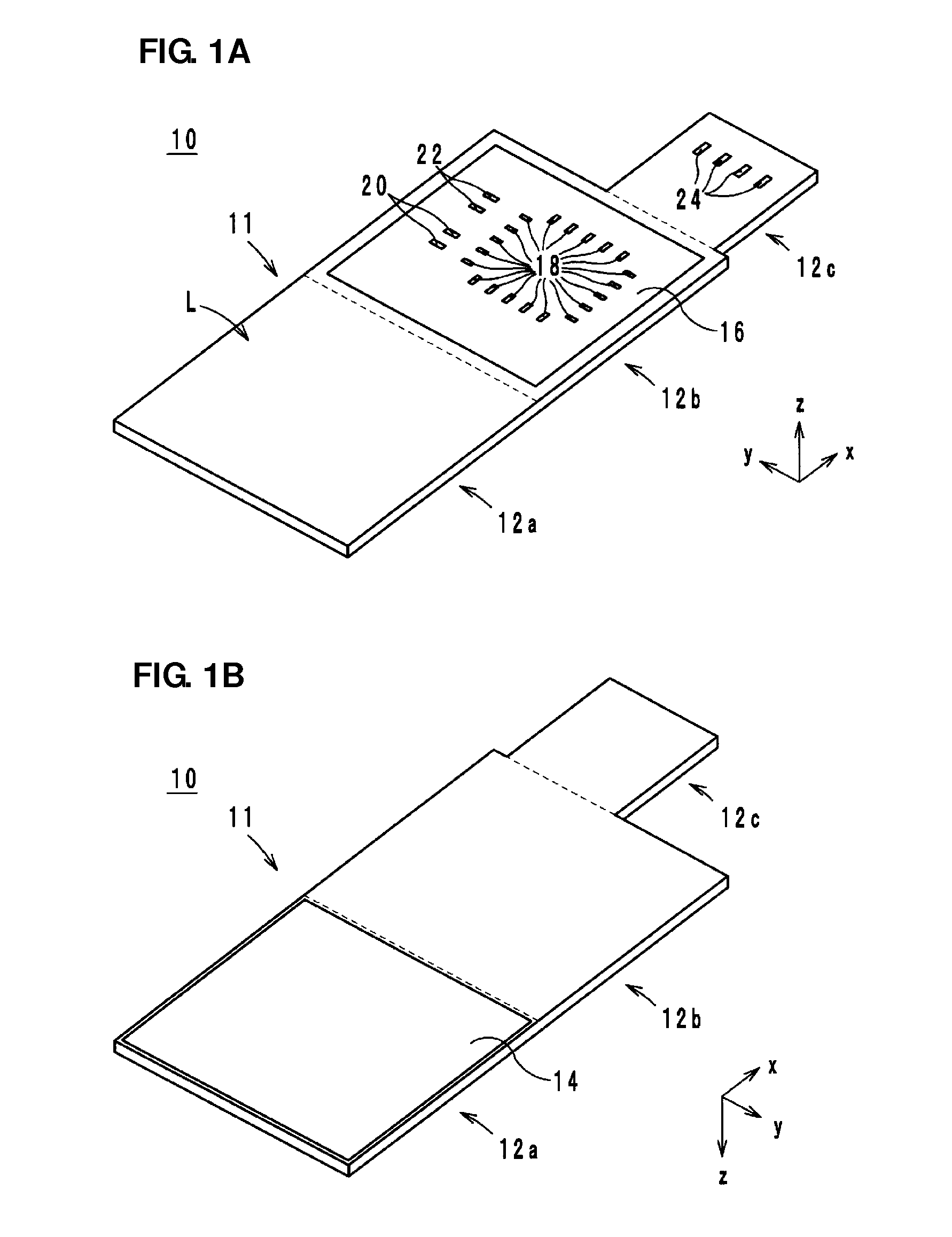
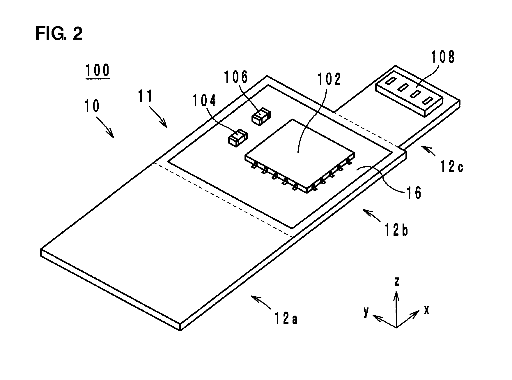
[0021]Hereinafter, a circuit board and a circuit module according to various preferred embodiments of the present invention will be described with reference to the drawings. FIGS. 1A and 1B are external perspective views of a circuit board 10 according to a preferred embodiment of the present invention. FIG. 2 is an external perspective view of a circuit module 100 that includes the circuit board 10 in FIGS. 1A and 1B. FIG. 3 is an exploded perspective view of the circuit board 10 in FIGS. 1A and 1B. FIG. 4 is a diagram illustrating the circuit module 100 in FIG. 2 is mounted in an electronic device. Hereinafter, a direction in which insulating material layers are laminated when producing the circuit board 10 is defined as a lamination direction. The lamination direction is defined as a z-axis direction, and a longitudin...


PUM


Abstract

A circuit board and a circuit module more accurately provide impedance matching between an antenna coil and an electronic component electrically connected to the antenna coil, and include a board body including board portions and a plurality of laminated insulating material layers made of a flexible material. An antenna coil includes coil conductors provided in the board portion. Wiring conductors are provided in the board portion and electrically connected to the antenna coil. The board portion has a structure that is less likely to deform than the board portion. An integrated circuit electrically connected to the wiring conductors is mounted on the board portion.

Description

BACKGROUND OF THE INVENTION[0001]1. Field of the Invention[0002]The present invention relates to a circuit board and a circuit module, and more specifically, relates to a circuit board and a circuit module each including an antenna coil.[0003]2. Description of the Related Art[0004]As an existing circuit board, for example, the flexible sheet described in International Publication No. 2007 / 015353 is known. Hereinafter, the flexible sheet will be described with reference to the drawing. FIG. 7 is a configuration diagram of the flexible sheet 500 described in International Publication No. 2007 / 015353.[0005]As shown in FIG. 7, the flexible sheet 500 is one sheet formed from a flexible material, and is composed of coil pattern portions 500a to 500d and a mounting portion 501. Coil conductors 502a to 502d are provided on the pattern portions 500a to 500d, respectively. The coil conductors 502a to 502d constitute an antenna coil.[0006]Further, a hard circuit board 600 is mounted on the mou...

Claims


Application Information

Patent Timeline
IPC IPC(8): H01Q1/38H01Q7/08
CPCH01L23/5387H05K2201/05H01L2223/6677H01L2924/3011H01Q1/20H01Q7/00H05K1/0233H05K1/0243H05K1/025H05K1/0281H05K1/165H05K1/189H05K3/4632H05K2201/09336H05K2201/10098H05K2201/10189H01L2924/0002H01L23/66H01Q7/06H01L2924/00H01Q1/38
Inventor KATO, NOBORUSASAKI, JUN
Owner MURATA MFG CO LTD
Why Eureka
Try Eureka