Deflection measuring device according to the interferometer principle

Inactive Publication Date: 2012-03-08
KROHNE MESSTECHNICK GMBH & CO KG
View PDF8 Cites 5 Cited by
  • Summary
  • Abstract
  • Description
  • Claims
  • Application Information

AI Technical Summary

Benefits of technology

[0008]Thus, it is a primary object of the present invention to provide a deflection measuring device according to the interferometric pr

Problems solved by technology

The high sensitivity of the interferometric measuring method, however, does not only have advantages, but also disadvantages, which, due to high sensitivity, always has the risk that undesired disturbance signals are created, which often occurs in the rough surroundings of process measurement.
Here, the problem is that the deflection body with the first or second fiber-optic means attached on it has to be arrange

Method used


Image

  • Deflection measuring device according to the interferometer principle
  • Deflection measuring device according to the interferometer principle
  • Deflection measuring device according to the interferometer principle

Examples


Embodiment Construction

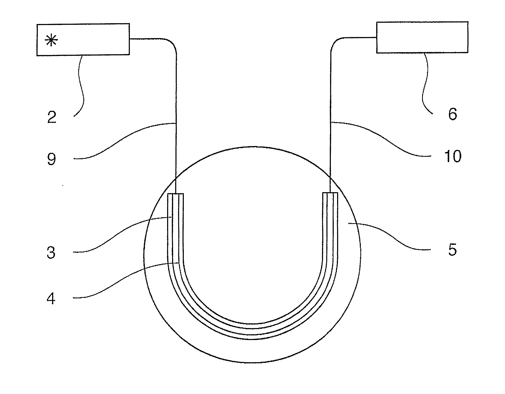
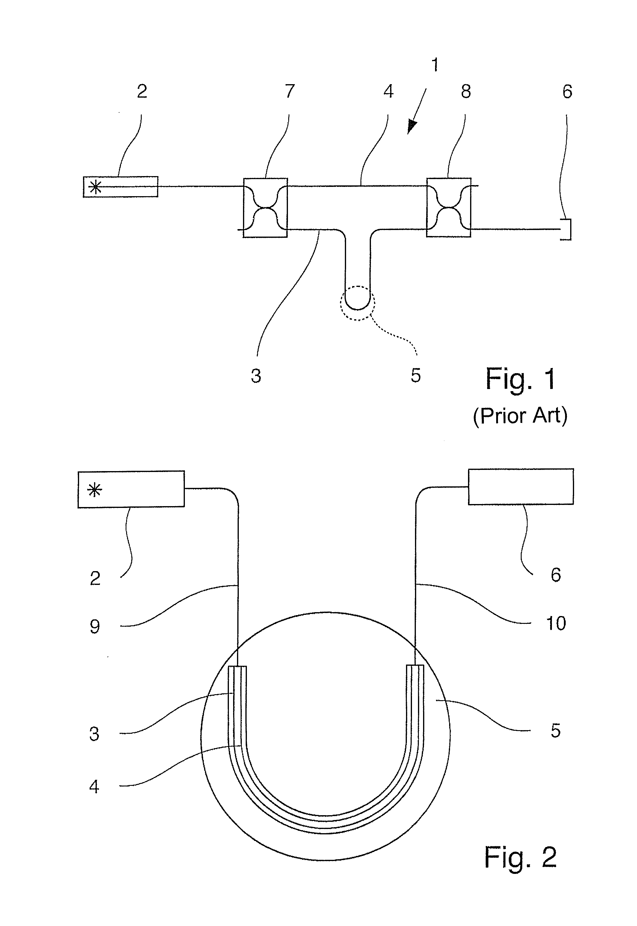
[0026]A deflection measuring device known from the prior art, which functions according to the interferometer principal and is presently used for differential pressure measurement in a vortex flowmeter is shown in FIG. 1. The deflection measuring device 1 has a radiation source 2, a first fiber-optic means 3 implementing a first light path and a second fiber-optic means 4 implementing a second light path. The deflection body 5 is a flat membrane in the present case, which is surrounded by a medium that flows through a flowmeter (not shown).

[0027]The first fiber-optic means 3 and the second fiber-optic means 4 are impinged on the input side with interference-capable radiation from the radiation source 2, wherein, in the present case, the first fiber-optic means 3 is joined with the deflection body 5 designed as a membrane, normally, by optical couplers 7, 8, which initially transmit radiation present only in the second fiber-optic means 4 also to the first fiber-optic means 3, so tha...


PUM


Abstract

An interferometer type deflection measuring device having a radiation source, a first fiber-optic means forming a first light path, a second fiber-optic means forming a second light path, a deflection body and an evaluation circuit, the first and second fiber-optic means receiving radiation from the radiation source on an input side, and radiation guided in the first and second fiber-optic means, respectively, being brought together on an output side with interference radiation being conveyed to the evaluation circuit for evaluation. The first fiber-optic means and the second fiber-optic means are arranged only on the deflection body, at least one of the first and second fiber-optic means being connected on the input side to the beam source with a single feed optical fiber and at least one of the first and second fiber-optic means being connected on the output side to the evaluation circuit by a single evaluation optical fiber.

Description

BACKGROUND OF THE INVENTION[0001]1. Field of the Invention[0002]The invention relates to a deflection measuring device according to the interferometer principle having a radiation source, a first fiber-optic means implementing a first light path, a second fiber-optic means implementing a second light path, a deflection body and an evaluation circuit, wherein the first fiber-optic means and the second fiber-optic means can be impinged with interference-capable radiation from the radiation source on the input side, wherein at least the first fiber-optic means is connected with the deflection body and wherein the first partial radiation guided in the first fiber-optic means and the second partial radiation guided in the second fiber-optic means are brought together on the output side and the interference radiation is conveyed to the evaluation circuit and evaluated by the evaluation circuit.[0003]2. Description of Related Art[0004]Deflection measuring devices using the interferometer p...

Claims


Application Information

Patent Timeline
IPC IPC(8): G01B9/02
CPCG01B11/161G01F1/3254G02B6/29352G02B6/02338G02B6/02042G01F1/3259
Inventor KRISCH, HENRIK
Owner KROHNE MESSTECHNICK GMBH & CO KG
Why Eureka
Try Eureka