Protective covering for an electronic device

a technology for electronic devices and protective covers, applied in the direction of electrical apparatus casings/cabinets/drawers, instruments, manufacturing tools, etc., can solve the problems of prone to scratching or damage, affecting the installation of main products, and affecting the use of main products, so as to facilitate simultaneous folding and increase rigidity. , the effect of increasing rigidity

Inactive Publication Date: 2012-03-08
ZAGG
View PDF4 Cites 41 Cited by
  • Summary
  • Abstract
  • Description
  • Claims
  • Application Information

AI Technical Summary

Benefits of technology

[0011]In another embodiment of the invention, a cover for an electronic device is provided with a first layer comprising a flexible film having opposing first and second sides. The cover further comprises a second flexible layer removably disposed about substantially all of the first side of the film. Additionally, the cover has a substantially inelastic third layer removably disposed about substantially all of the second side of the film. The third layer is more rigid than the second layer so as to facilitate simultaneous folding of the second and third layers to create a tab member while exposing a portion of the film for tacking.
[0012]In one embodiment of the invention, a method of covering an electronic device is disclosed. The method comprises obtaining a first layer comprising a flexible film with opposing first and second sides. The method further comprises obtaining a second flexible layer, the second layer being removably disposed about substantially all of the first side of the film. The method further comprises obtaining a third substantially inelastic layer, wherein the third layer is removably disposed about substantially all of the second side of the film. The third layer is more rigid than the second layer and facilitates folding of the second layer away from the first layer. The method further comprises folding an end portion of the second layer away from the first layer to create a tab member while simultaneously exposing a portion of the first layer for tacking to a device.

Problems solved by technology

Due to the common use of these devices, they are prone to scratching or damage from use.
Application of these films, however, has posed significant challenges for users.
While release liners serve the purpose of protecting the adhesive, a single liner often makes installation of the main product difficult in several ways.
For example, in the case of protection films, removing the release liner prior to installation leaves the adhesive exposed to dust, lint, and fingerprints.
Without liquid, smoothly laying down the film in the correct position upon the first adherence is nearly impossible.
This makes alignment very difficult and leaves the film susceptible to dust and fingerprints.
In other cases, the film may be aligned properly but may entrain air pockets or other undesirable matter.
Still other problems are encountered during installation of the film due to the elasticity inherent in films.
Specifically, while installing a film, a user will often stretch the film so that it extends beyond its intended length.
In each case, however, there is no fully reliable system for correct alignment on the first attempt.
In the case of a larger material over the covering that can be temporarily tacked down, the alignment issue is only partially solved, and there is not a simple method for removing the liner once in place without fully exposing the adhesive coating.

Method used


Image

  • Protective covering for an electronic device
  • Protective covering for an electronic device
  • Protective covering for an electronic device

Examples


Embodiment Construction

)

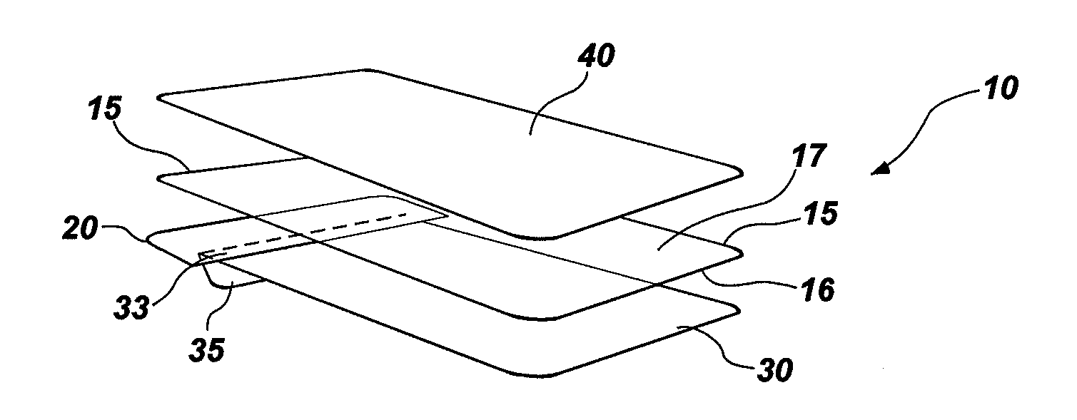
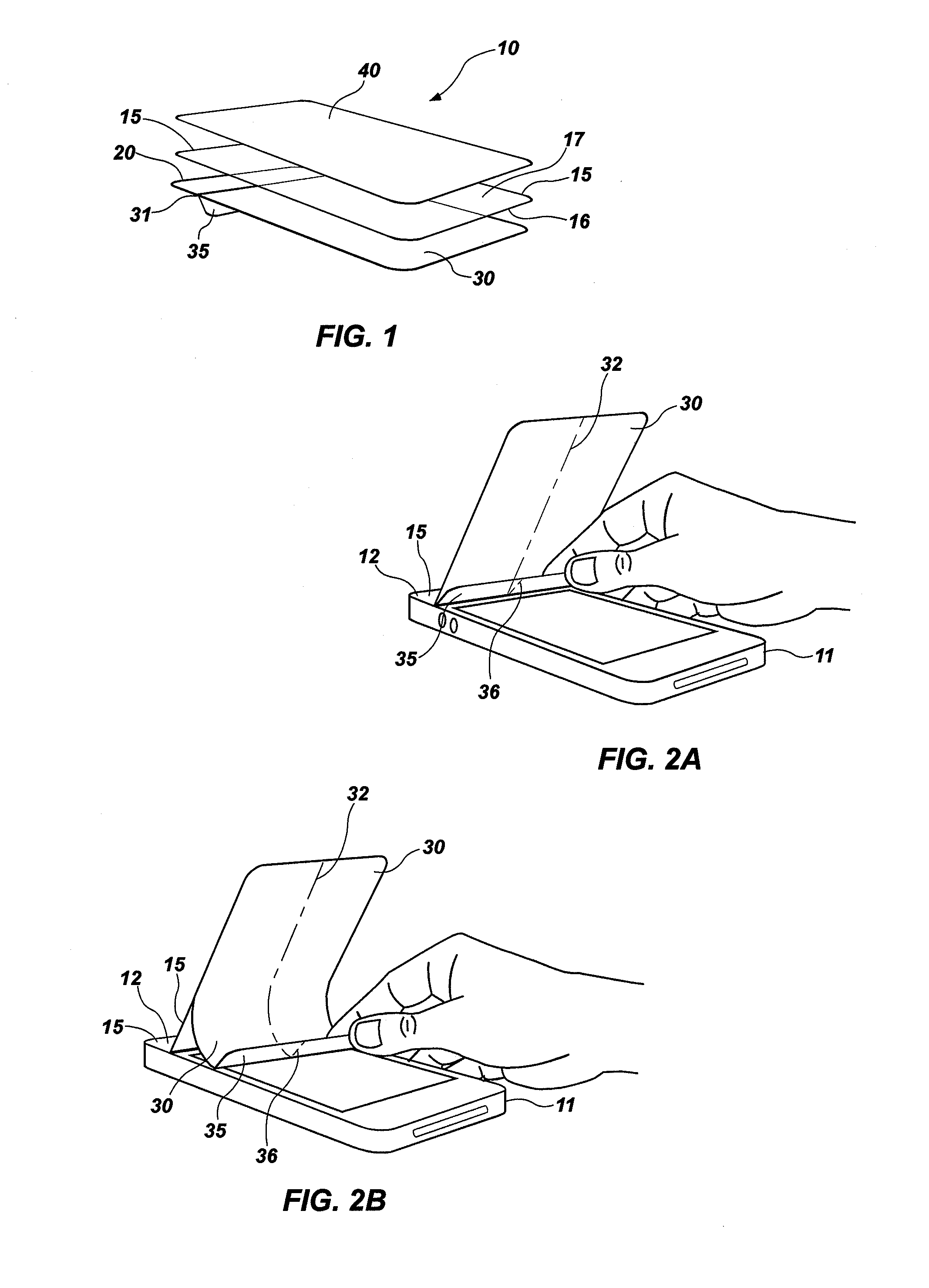
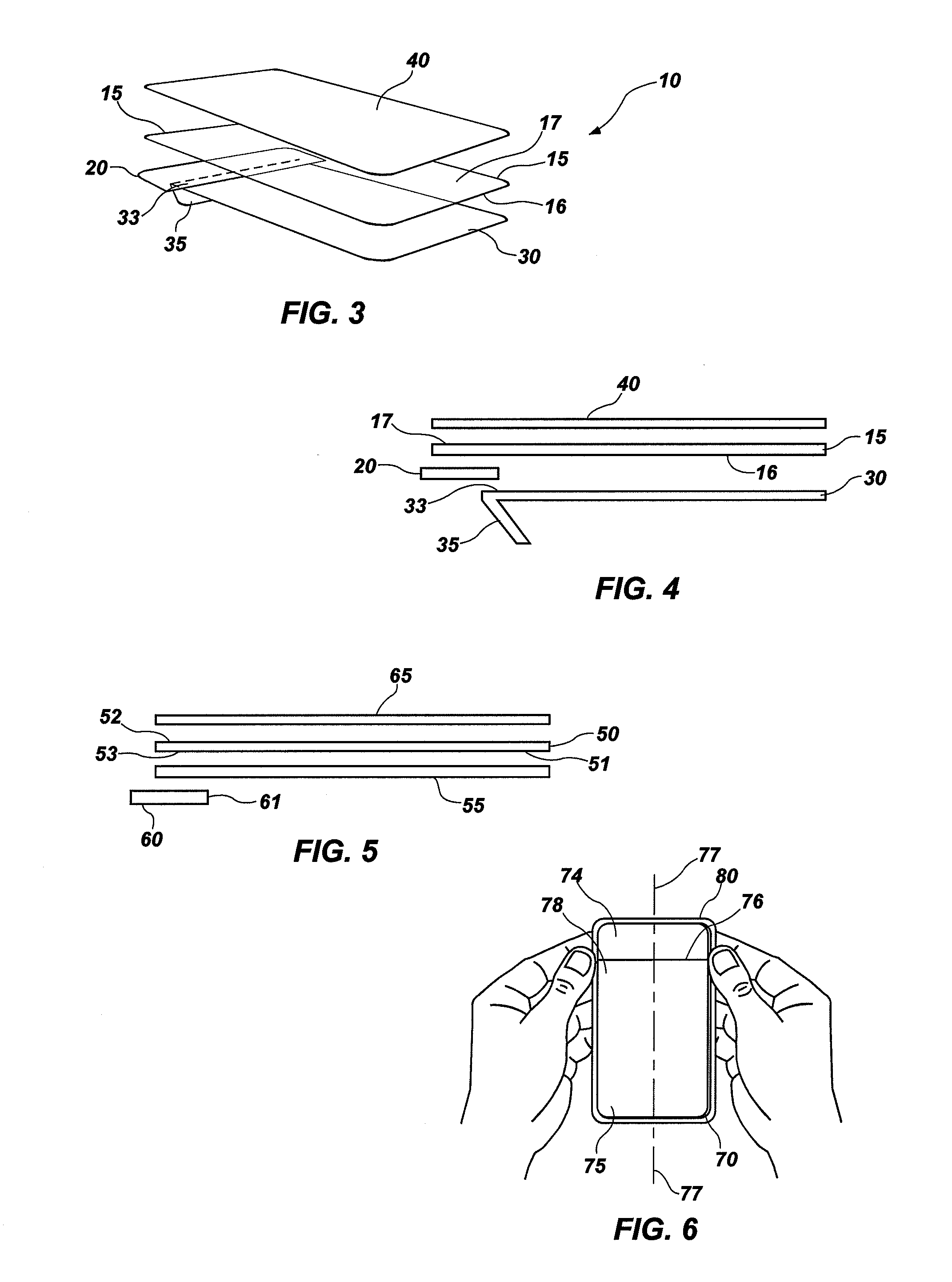
[0020]The following detailed description of exemplary embodiments of the invention makes reference to the accompanying drawings, which form a part hereof and in which are shown, by way of illustration, exemplary embodiments in which the invention may be practiced. While these exemplary embodiments are described in sufficient detail to enable those skilled in the art to practice the invention, it should be understood that other embodiments may be realized and that various changes to the invention may be made without departing from the spirit and scope of the present invention. Thus, the following more detailed description of the embodiments of the present invention is not intended to limit the scope of the invention, as claimed, but is presented for purposes of illustration only to describe the features and characteristics of the present invention, and to sufficiently enable one skilled in the art to practice the invention. Accordingly, the scope of the present invention is to be de...


PUM

PropertyMeasurementUnit
thicknessesaaaaaaaaaa

Abstract

A cover for an electronic device is disclosed comprising a plurality of layers including a first layer having opposing first and second sides configured to cover an outer surface of an electronic device. A second layer is removably disposed about a first portion of the first side of the first layer. A tab member is disposed about or created on the cover to facilitate installation of the first layer about the surface of the electronic device.

Description

CLAIM OF PRIORITY[0001]This application claims priority to U.S. Provisional Patent Application No. 61 / 379,151 filed on Sep. 1, 2010 entitled “Dry Applied Cell Phone Film” which is incorporated herein by reference in its entirety.FIELD OF THE INVENTION[0002]The present invention relates generally to a protective cover for electronic devices and particularly a cover that improves and simplifies installation of the protective cover on such devices.BACKGROUND[0003]In recent years, technological developments have resulted in an explosion of electronic devices used in numerous facets of commercial and every day activities. Specifically, due to advances in technology and improvements in methods of manufacture, portable electronic devices such as cell phones, smart phones, or tablet computers, for example, have become affordable for a significantly greater percentage of the population and are used for an increased variety of purposes. Due to the common use of these devices, they are prone t...

Claims


Application Information

Patent Timeline
Patent Type & Authority Applications(United States)
IPC IPC(8): G06F1/16B23P11/00
CPCC09J7/0239Y10T29/49826G06F1/1637C09J7/22C09J7/30B32B37/16B32B37/12B32B38/10B32B38/0004B32B37/0076B32B2307/412H04B1/3888
Inventor CHAVES, TIMOTHY ANDREWFELLOWS, STEVEN SMITH
Owner ZAGG
Why Eureka
Try Eureka