Lane line estimating apparatus

a technology of estimating apparatus and lane line, which is applied in the field of lane line estimating apparatus, can solve problems such as errors in recognition

Active Publication Date: 2012-03-08
SUBARU CORP
View PDF9 Cites 45 Cited by
  • Summary
  • Abstract
  • Description
  • Claims
  • Application Information

AI Technical Summary

Benefits of technology

[0015]According to the present invention, the lane-line detection points are detected on the left side and on the right side of the driving lane, the lane-line candidate points are set on the positions of the lane-line width for each of the predetermined lane-line types on the opposite lane line, using the lane-line detection points as starting points. The virtual lines are set on the left side and on the right side of the driving lane from the curve approximation equation that is set based upon the lane-line detection points and the lane-line candidate points, and the dispersio

Problems solved by technology

Therefore, a lane line can be highly precisely estimated, even when a lane line on a road is a double white line, or even under a situation in wh

Method used


Image

  • Lane line estimating apparatus
  • Lane line estimating apparatus
  • Lane line estimating apparatus

Examples


Embodiment Construction

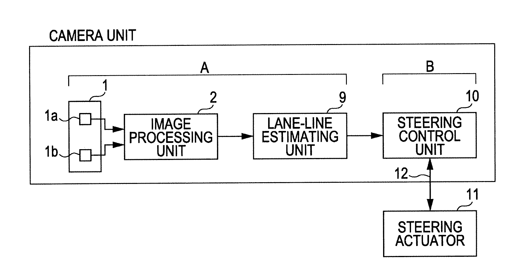
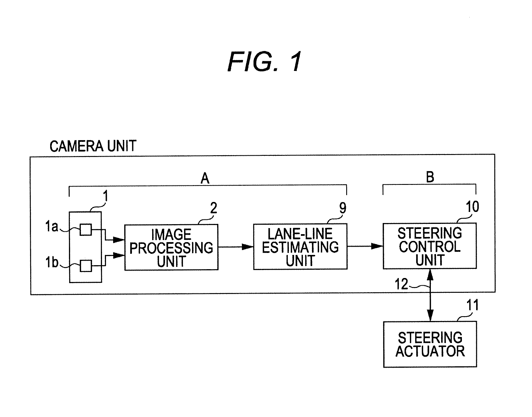
[0029]Hereinafter, an embodiment of the present invention will be described with reference to the drawings. A driving control apparatus illustrated in FIG. 1 includes an image processing system A and a steering control system B, wherein the image processing system A includes an imaging unit 1, an image processing unit 2, and a lane-line estimating unit 9, while the steering control system B includes a steering control unit 10 and a steering actuator 11. In the present embodiment, the image processing system A and the steering control unit 10 are mounted on a camera unit. Examples of the steering actuator 11 include an electric motor and a hydraulic motor.

[0030]The steering control unit 10 is mainly composed of a microcomputer. The steering control unit 10 is connected to the steering actuator 11 via an in-vehicle communication line 12 such as CAN (Controller Area Network) so as to be capable of making a two-way communication. The steering control unit 10 sets a steering angle such t...


PUM


Abstract

A fixed data memory stores data of a normal lane width between lane lines and a narrow lane width between inner guide lines of double white lines. A lane-line candidate setting section detects lane-line detection points on both sides of a driving lane using a captured image, and sets lane-line candidate points on the opposite lane lines at spaces of the widths and therebetween, using the detection points as starting points. A curve approximation processing section sets virtual lines on both sides of the driving lane from a curve approximation equation obtained using the detection and candidate points. A lane-line position setting section obtains dispersions of the candidate points to the left and right virtual lines, and estimates the type of at least one of the left and right virtual lines.

Description

CROSS-REFERENCE TO RELATED APPLICATIONS[0001]The present application claims priority from Japanese Patent Application No. 2010-201204 filed on Sep. 8, 2010, the entire contents of which are hereby incorporated by reference.BACKGROUND OF THE INVENTION[0002]1. Field of the Invention[0003]The present invention relates to a lane line estimating apparatus that sets a virtual line on a driving lane corresponding to a lane line based upon an external environment ahead captured by imaging unit mounted on a vehicle.[0004]2. Description of the Related Art[0005]There have conventionally been known driving support apparatuses making various controls during driving on an express highway. There is the one of the driving support apparatuses described above that makes a driving control in which a driving environment ahead of a vehicle is detected, lane lines defining the left side and the right side of a driving lane on which the vehicle runs are detected based upon the detected driving environment...

Claims


Application Information

Patent Timeline
IPC IPC(8): G06K9/00
CPCB60W30/12G06K9/00798B60W2420/42G06V20/588
Inventor OYAMA, HAJIME
Owner SUBARU CORP
Why Eureka
Try Eureka