Method, apparatus and system for transmitting and receiving client signals

a technology of transmitting and receiving client signals, applied in the field of optical networks, can solve the problems of serious waste of inconvenient management of client signals by otn, and achieve the effect of facilitating otn to manage each client signal and saving otn transport channel bandwidth

Active Publication Date: 2012-03-08
HUAWEI TECH CO LTD
View PDF12 Cites 12 Cited by
  • Summary
  • Abstract
  • Description
  • Claims
  • Application Information

AI Technical Summary

Benefits of technology

[0007]The embodiments of the present invention provides a method, apparatus and system for transmitting and receiving client signals, so that the rate of the client signals and the rate of the ODUk can be accurately matched, the bandwidth of the OTN transport channel can be saved, and a strong management can be achieved for each client signal.
[0014]In the embodiments of the present invention, at the transmitting end, a low-order ODU set having rates increased in order is configured, correspondence relations between the client signals to be transmitted and the low-order ODUs in the low-order ODU set are established by rate, and the client signals to be transmitted are mapped into corresponding low-order ODUs in the low-order ODU set. Thus, the rates of the client signals can be accurately matched with the rates of the low-order ODUs in the low-order ODU set, so that the bandwidth of the OTN transport channel can be saved.
[0015]In addition, the transmitting end may, based on the correspondence relation between the client signals to be transmitted and the low-order ODUs having rates increased in order in the low-order ODU set, map multiple client signals to corresponding low-order ODUs in the low-order ODU set, then map each low-order ODUs in the low-order ODU set to different timeslots of the high-order OPUs in the high-order OPU set, to be transferred to the OTN through data frame for transmission, so as to facilitate the OTN to manage each client signal. Furthermore, the sub data units in the low-order ODU set employ the identical frame structure, so that a strong management can be achieved for each type of client signal.

Problems solved by technology

Thus the bandwidth of OTN transport channel is seriously wasted.
Meanwhile, for multiple client signals, the transmitting end has to bundle these multiple client signals together and map them into a single ODUk, which is inconvenient for the OTN to manage each client signal.

Method used


Image

  • Method, apparatus and system for transmitting and receiving client signals
  • Method, apparatus and system for transmitting and receiving client signals
  • Method, apparatus and system for transmitting and receiving client signals

Examples


first embodiment

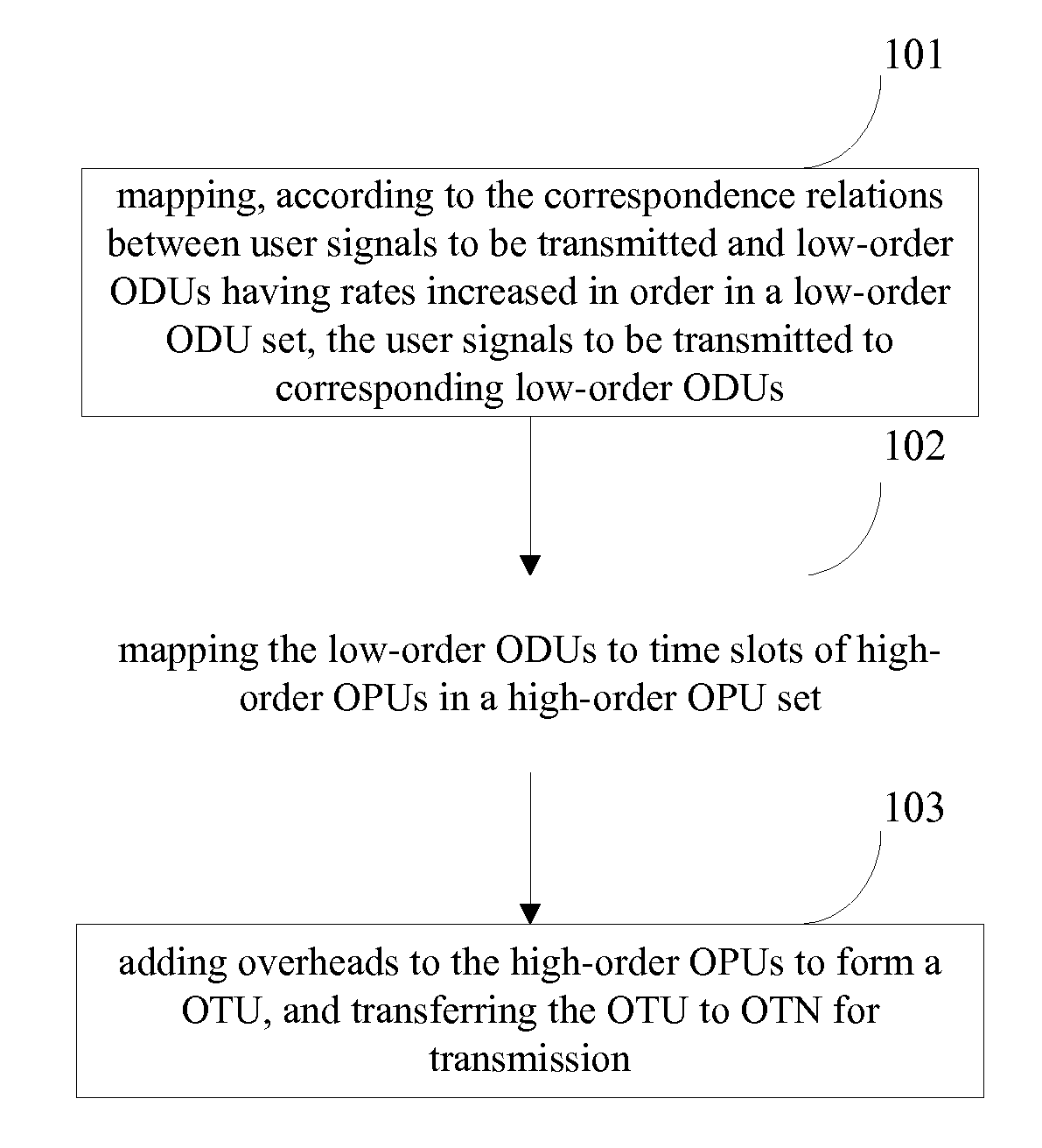
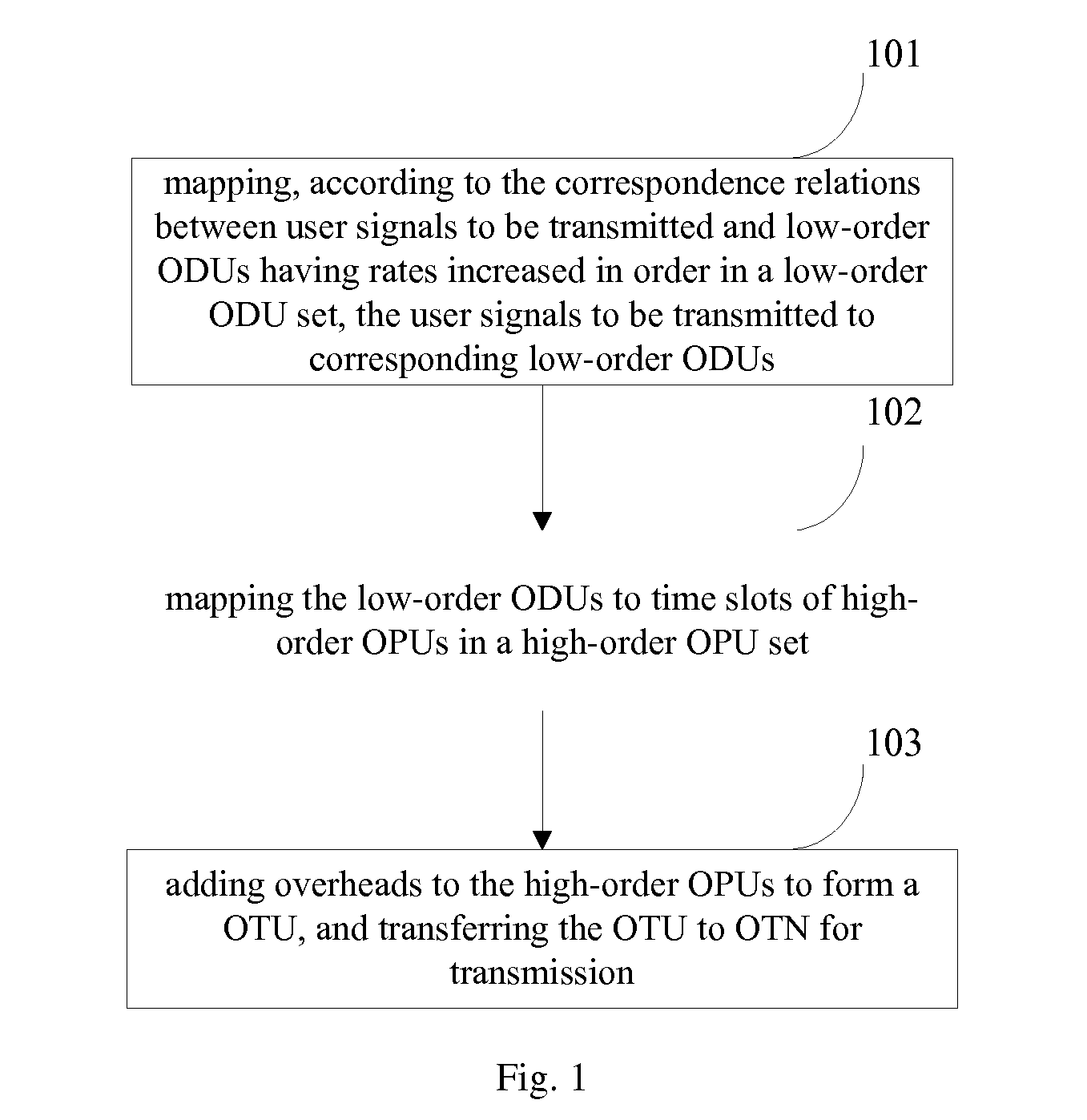
[0025]Referring to FIG. 1, illustrated is a flowchart of a client signal transmitting method according to the present invention, which includes:

[0026]Step 101: mapping, according to the correspondence relations between client signals to be transmitted and low-order Optical Channel Data Units (ODUs) having rates increased in order in a low-order ODU set, the client signals to be transmitted to corresponding low-order ODUs;

[0027]Step 102: mapping the low-order ODUs to timeslots of high-order Optical Channel Payload Units (OPUs) in a high-order OPU set; and

[0028]Step 103: adding overheads to the high-order OPUs to form an Optical Channel Transport Unit (OTU), and transferring the OTU to an Optical Transport Network (OTN) for transmission.

[0029]From the above embodiment, it can be seen that by configuring a low-order ODU set with rates increased in order, and establishing correspondence relations between the client signals and the low-order ODUs in the low-order ODU set by rate, a clien...

second embodiment

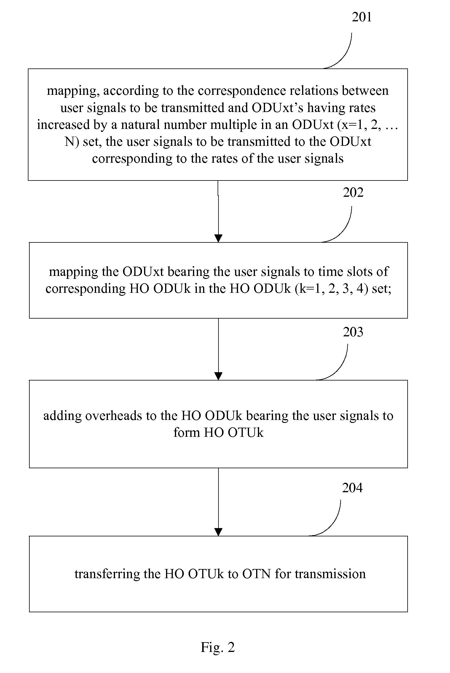
[0030]Referring to FIG. 2, illustrated is a flowchart of a client signal transmitting method according to the present invention, which includes:

[0031]Step 201: mapping, according to the correspondence relations between client signals to be transmitted and Optical Channel Data Unit-xt (ODUxt) (x=1, 2, . . . N) having rates increased by a natural number multiple in an ODUxt set, a client signal to be transmitted to the ODUxt corresponding to the rate of the client signal; where, an ODUxt (x=1, 2, . . . N) set having rates increased in order is configured. With respect to a specific client signal, an ODUxt corresponding to the rate of the client signal is selected from the ODUxt (x=1, 2, . . . N) set according to the rate of the client signal, and then the client signal is mapped into the ODUxt.

[0032]Preferably, in the ODUxt (x=1, 2, . . . N) set, the rate of a minimum rate granularity ODU1t is the rate of a minimum timeslot granularity in a High Order Optical Channel Data Unit-k (HO O...

third embodiment

[0043]A flowchart for a client signal transmitting method according to the present invention is described in detail with reference to FIG. 3. In the present embodiment, the rate of ODU1t is 1.304449692 Gbit / s, HO ODU1 is divided into 2 timeslots, HO ODU2 is divided into 8 timeslots, HO ODU3 is divided into 32 timeslots, and HO ODU4 is divided into 80 timeslots. Four client signals are to be transmitted, including 2 10GE LAN, 1 STM-64, and 1 ODU2. The method includes:

[0044]Step 301: mapping, according to the correspondence relations between client signals to be transmitted and ODUxts having rates increased by a natural number multiple in the ODUxt (x=1, 2, . . . N) set, the 4 client signals to 4 ODU8ts respectively, through GMP asynchronous mapping.

[0045]In the present embodiment, the rate of ODU1t is 1.304449692 Gbit / s, therefore 4 client signals are mapped into an ODU8t according to the correspondence relations in Table 1 between the current client signals and the ODUxts in the ODU...


PUM


Abstract

The present invention provides a method, apparatus and system for transmitting and receiving a client signal. The method for transmitting a client signal includes, at the transmitting end, mapping a client signal to be transmitted to a corresponding low-order Optical Channel Data Unit (ODU) in a low-order ODU set, wherein low-order ODUs in the low-order ODU set having rates increased in order, and having rate correspondence relations with the client signals; mapping the low-order ODU to a timeslot of a high-order Optical Channel Payload Unit (OPU) in a high-order OPU set; and adding overheads to the high-order OPU to form an Optical Channel Transport Unit (OTU), and transferring the OTU to an Optical Transport Network (OTN) for transmission.

Description

CROSS-REFERENCE TO RELATED APPLICATIONS[0001]This application is a continuation of U.S. patent application Ser. No. 12 / 721,338, filed Mar. 10, 2010, which is a continuation of International Application No. PCT / CN2009 / 072449, filed Jun. 25, 2009. The international application claims priority to Chinese Patent Application No. 200810111493.0, filed Jun. 26, 2008. The applications are hereby incorporated by reference in their entireties.FIELD OF THE INVENTION[0002]The present invention relates to the field of optical network, and particularly, to a method, apparatus and system for transmitting and receiving client signals.BACKGROUND[0003]As the core technology of the next generation transport networks, the Optical Transport Network (OTN) not only has abundant Operation Administration and Maintenance (OAM), strong Tandem Connection Monitor (TCM) and out-band Forward Error Correction (FEC) capability, but also can perform flexible scheduling and management of large volume service, and has...

Claims


Application Information

Patent Timeline
Patent Type & Authority Applications(United States)
IPC IPC(8): H04J14/00H04B10/06H04B10/04
CPCH04J3/1652H04J14/086H04J3/1664
Inventor DONG, LIMINWU, QIUYOUZHONG, QIWENYAO, ZHIYINGVISSERS, MAARTEN
Owner HUAWEI TECH CO LTD
Why Eureka
Try Eureka