
Delivery device for delivering a stent device

a technology for delivering devices and stents, which is applied in the field of delivery devices, can solve the problems of compromising deployment accuracy and affecting the structure of stent devices, and achieve the effect of undesirable deployment forces

Active Publication Date: 2012-03-08
CR BARD INC
View PDF3 Cites 42 Cited by
  • Summary
  • Abstract
  • Description
  • Claims
  • Application Information

AI Technical Summary

Benefits of technology

[0024]This arrangement of the stop allows a larger predetermined distance to be defined than if the stop was positioned axially within the stent device because the stent device will generally define a relatively compact structure.
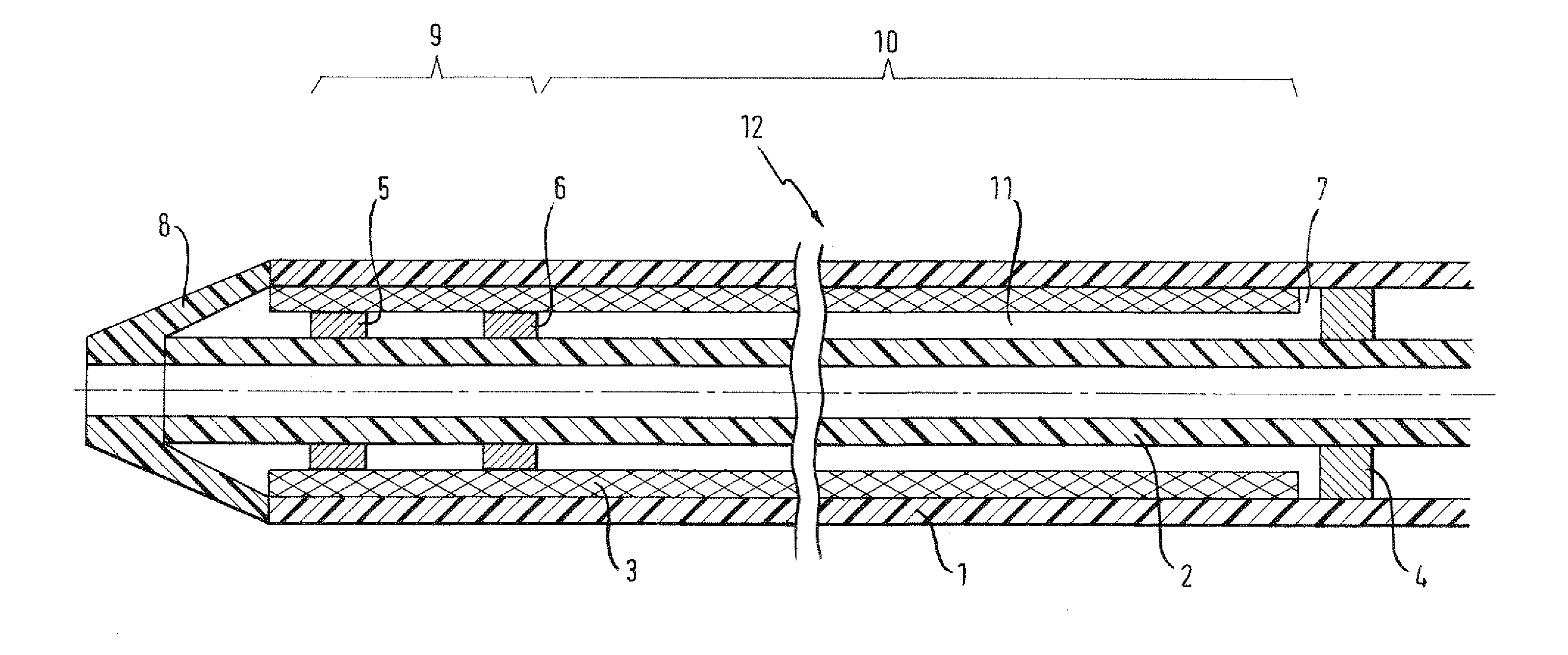
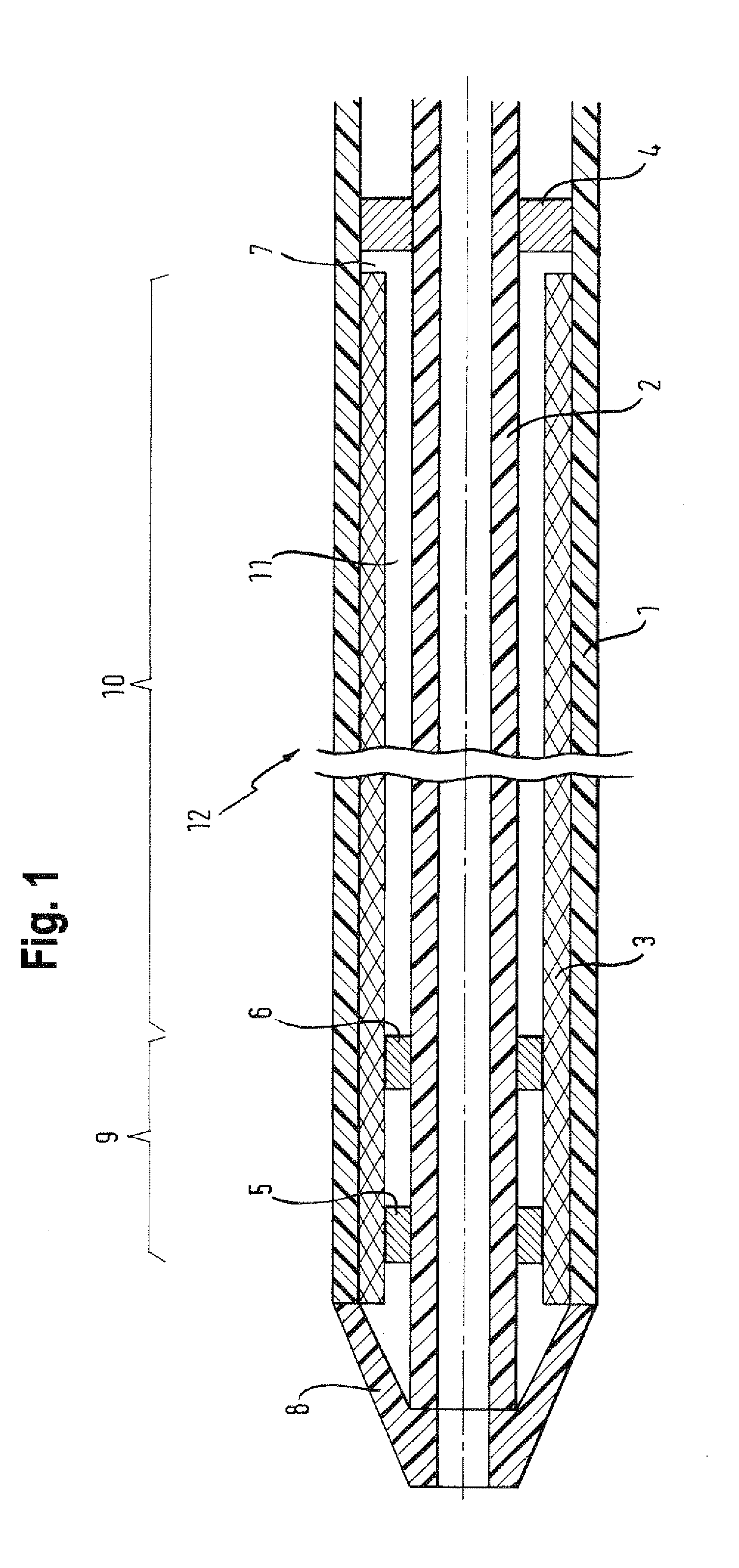
[0026]While in the prior art, protuberances extend radially from the inner member and are distributed the full length of the stent device, preferred embodiments of the present invention propose to provide at least one radial protuberance just at the distal portion, leaving the remaining portion free therefrom. In this way, the distal end of the stent device is appropriately positioned and the stent device is bulled out of the outer sheath from the front in a reduced deployment force manner.
[0032]The present invention is suitably used with stent have a length greater than 60 mm, greater than 100 mm, greater than 150 mm, greater than 170 mm or even greater than 200 mm. As explained above, it is with the longer stents that deployment forces can be undesirably great. Further, longer stents provide scope for longer movement of the remaining portion of the stent device with the outer sheath without compromising the integrity of the stent device. For this reason also, the distal portion of the stent device is within an end 35% of the stent device, an end 30% of the stent device, an end 25% of the stent device, an end 20% of the stent device or even an end 15% of the stent device.
[0035]The outer sheath is preferably made of a polymer material, which may stretch upon deployment force being applied to retract the outer sheath from the stent device. This stretching would be a hindrance with prior art anchorage arrangements because it would cause radial contraction of the outer sheath onto the stent device, thereby tightening the grip on the stent device and correspondingly increasing the deployment force. In preferred anchorage arrangements of the present invention, however, a space is provided radially between the remaining portion of the stent device and the inner member and extending axially the length of the stent device. This allows the stent device to contract with the outer sheath as well as move axially therewith so as to provide a limited contribution to frictional movement between the stent device and the outer sheath, thereby reducing deployment force.

Problems solved by technology

With this proximal stop arrangement, the friction tends to foreshorten the stent device, which compromises deployment accuracy.
Furthermore, the total force on the proximal end of the stent device could damage the structure of the stent device, particularly as longer stent devices are used.

Method used


Image

  • Delivery device for delivering a stent device
  • Delivery device for delivering a stent device

Examples


Embodiment Construction

[0038]FIG. 1 discloses a delivery device 12 for delivering a stent device 3 to a target treatment site. The stent device 3 is mounted onto an inner catheter 2 (inner member) that extends radially within and axially through the stent device 3. The inner catheter 2 has an inner lumen extending axially therethrough for passage of a guide wire (not shown). The stent device is held 3 in an axially compact, delivery configuration by an outer sheath 1 mounted radially over the stent device 3 and extending axially therealong. The delivery device has a tapered distal tip 8. An actuation system (not shown) is included at a proximal handle portion to actuate retraction of the outer sheath 1 from over the stent device 3 to release the stent device 3 to radially expand to a deployed configuration.

[0039]An anchorage is provided for holding the stent device 3 axially relative to the inner catheter 3 while the outer sheath 1 is axially retracted in order to release the stent device 3 to expand to a...


PUM


Abstract

A delivery device (12) for delivering a stent device (3) in a reduced profiled delivery configuration is provided. A distal region (9) of the stent device is axially anchored to an inner catheter (2) by annular rings (5, 6) about the inner catheter. A remaining portion (10) of the stent device is spaced radially from the inner catheter. A proximal stop (4) is spaced axially from a proximla end of the stent device. The stent device is maintained in the reduced profile delivery configuration by a retractable outer sheath (1).

Description

FIELD OF THE INVENTION[0001]The present invention is concerned with a delivery device for delivering a stent device to a target site. The delivery device includes an outer sheath for maintaining the stent device in a reduced profile delivery configuration. The stent device is held on an inner catheter extending through a lumen of the stent device. The outer sheath may be retracted as the stent device is held on the inner catheter so as to release the stent device to radially expand to a deployed configuration.BACKGROUND OF THE INVENTION[0002]Stent devices are useful for holding open bodily lumens of a human or animal patient. Of particular interest to the present invention are stent devices for holding open vascular lumens, such as veins or arteries, of a human patient.[0003]A self-expanding stent device of interest to the present invention is compacted into a reduced profile delivery configuration and mounted about an inner catheter. The stent device is made of a shape memory mater...

Claims


Application Information

Patent Timeline
Patent Type & Authority Applications(United States)
IPC IPC(8): A61F2/84A61F2/95A61F2/958A61F2/966
CPCA61F2/95A61F2002/9583A61F2/966A61F2002/9665A61F2250/0021
Inventor DORN, JURGENWALTER, BEATE
Owner CR BARD INC
Learn More