
Delivery device for delivering a stent device

a technology of stent device and delivery device, which is applied in the field of delivery device, can solve the problems of compromising deployment accuracy and affecting the structure of the stent device, and achieve the effect of ensuring deployment accuracy and reducing deployment for

Active Publication Date: 2014-03-25
CR BARD INC
View PDF175 Cites 12 Cited by
  • Summary
  • Abstract
  • Description
  • Claims
  • Application Information

AI Technical Summary

Benefits of technology

The present invention relates to a stent device with a stop that allows for a larger predetermined distance between the stop and the stent device, which is compact. The invention also proposes the use of a distal protuberance to appropriately position the stent device and reduce the deployment force. The stent device can have a length greater than 60 mm, and the distal portion of the stent device is within an end 35% of the stent device. The outer sheath is made of a polymer material that can stretch upon deployment force being applied to retract the outer sheath from the stent device. This stretching would cause radial contraction of the outer sheath onto the stent device, but the invention provides a space between the remaining portion of the stent device and the inner member to allow for limited frictional movement between the stent device and the outer sheath, thereby reducing the deployment force.

Problems solved by technology

With this proximal stop arrangement, the friction tends to foreshorten the stent device, which compromises deployment accuracy.
Furthermore, the total force on the proximal end of the stent device could damage the structure of the stent device, particularly as longer stent devices are used.

Method used


Image

  • Delivery device for delivering a stent device
  • Delivery device for delivering a stent device

Examples


Embodiment Construction

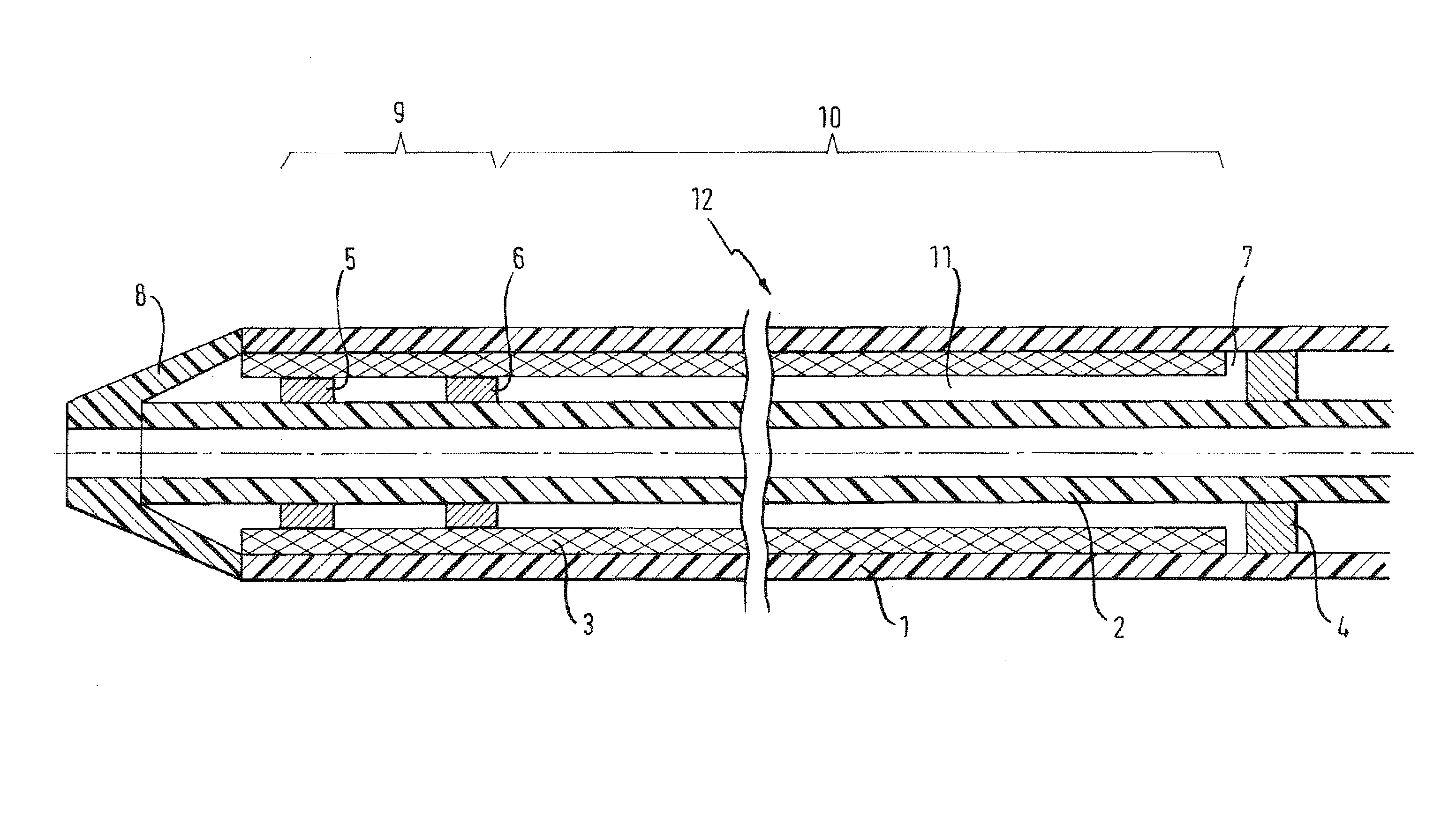
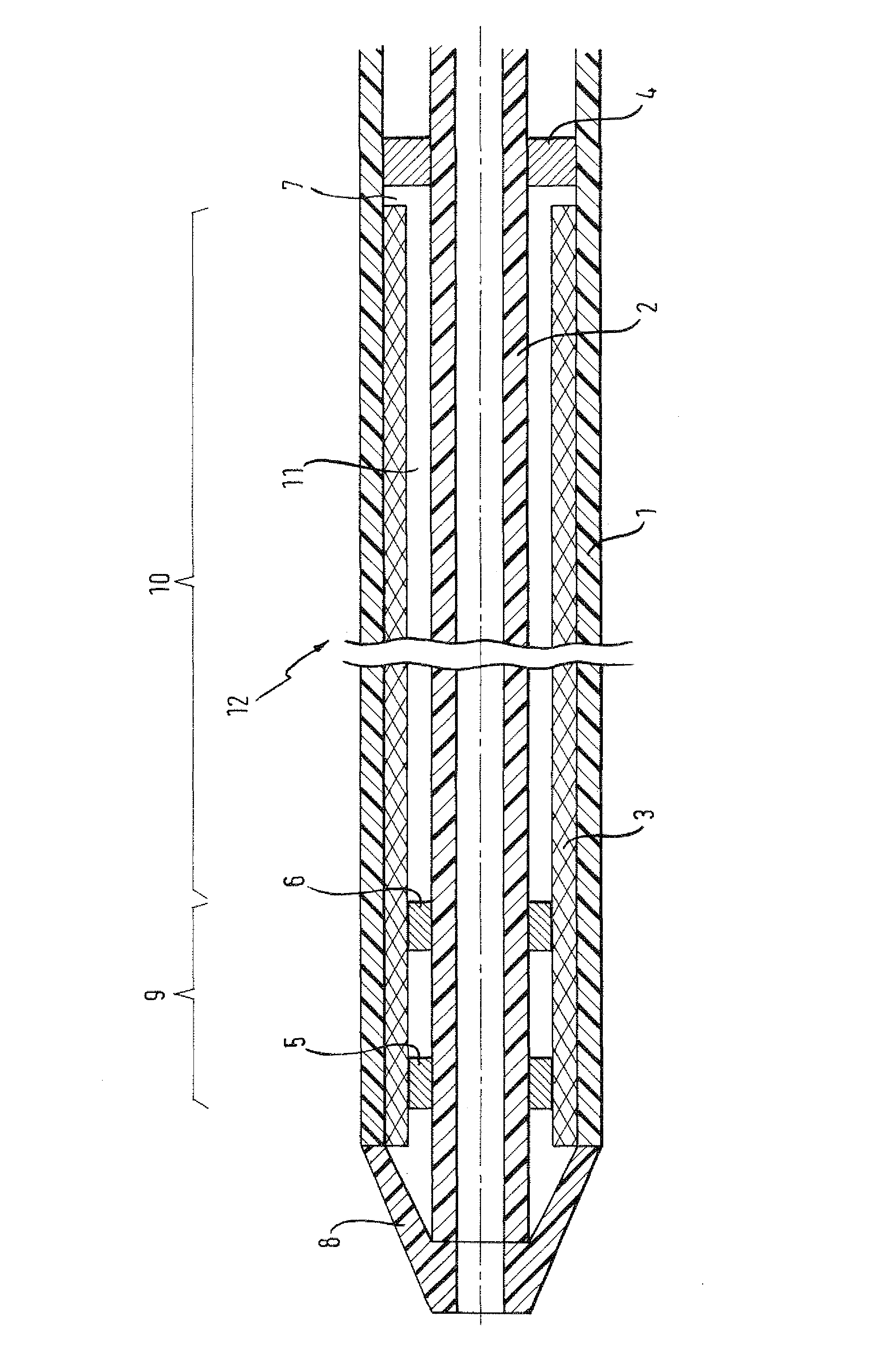
[0039]FIG. 1 discloses a delivery device 12 for delivering a stent device 3 to a target treatment site. The stent device 3 is mounted onto an inner catheter 2 (inner member) that extends radially within and axially through the stent device 3. The inner catheter 2 has an inner lumen extending axially therethrough for passage of a guide wire (not shown). The stent device is held 3 in an axially compact, delivery configuration by an outer sheath 1 mounted radially over the stent device 3 and extending axially therealong. The delivery device has a tapered distal tip 8. An actuation system (not shown) is included at a proximal handle portion to actuate retraction of the outer sheath 1 from over the stent device 3 to release the stent device 3 to radially expand to a deployed configuration.

[0040]An anchorage is provided for holding the stent device 3 axially relative to the inner catheter 3 while the outer sheath 1 is axially retracted in order to release the stent device 3 to expand to a...


PUM


Abstract

A delivery device (12) for delivering a stent device (3) in a reduced profiled delivery configuration is provided. A distal region (9) of the stent device is axially anchored to an inner catheter (2) by annular rings (5, 6) about the inner catheter. A remaining portion (10) of the stent device is spaced radially from the inner catheter. A proximal stop (4) is spaced axially from a proximal end of the stent device. The stent device is maintained in the reduced profile delivery configuration by a retractable outer sheath (1).

Description

PRIORITY[0001]This application is a U.S. national stage application under 35 USC §371 of International Application No. PCT / EP2010 / 050910, filed Jan. 27, 2010, claiming priority to United Kingdom Patent Application No. 0901496.0, filed Jan. 29, 2009, and to U.S. Provisional Application No. 61 / 148,188, filed Jan. 29, 2009, each of which is incorporated by reference in its entirety into this application.FIELD OF THE INVENTION[0002]The present invention is concerned with a delivery device for delivering a stent device to a target site. The delivery device includes an outer sheath for maintaining the stent device in a reduced profile delivery configuration. The stent device is held on an inner catheter extending through a lumen of the stent device. The outer sheath may be retracted as the stent device is held on the inner catheter so as to release the stent device to radially expand to a deployed configuration.BACKGROUND OF THE INVENTION[0003]Stent devices are useful for holding open bod...

Claims


Application Information

Patent Timeline
Patent Type & Authority Patents(United States)
IPC IPC(8): A61F2/95A61F2/966A61F2/958
CPCA61F2002/9583A61F2/95A61F2/966A61F2002/9665A61F2250/0021
Inventor DORN, JURGENWALTER, BEATE
Owner CR BARD INC
Learn More