Accelerator reaction force control apparatus

a technology of reaction force and accelerator pedal, which is applied in the direction of mechanical control devices, process and machine control, instruments, etc., can solve the problems of unsatisfactory behavior ultimately, accelerator pedal acting erratically against the intent of the driver, etc., and achieves the effect of increasing reaction force, reducing fuel consumption, and reducing fuel consumption

Active Publication Date: 2012-03-08
NISSAN MOTOR CO LTD
View PDF3 Cites 17 Cited by
  • Summary
  • Abstract
  • Description
  • Claims
  • Application Information

AI Technical Summary

Benefits of technology

[0010]In view of the above technology and according to one aspect of the present disclosure, an accelerator reaction force control apparatus is provided that comprises an accelerator position detecting device, a reaction force varying device and a threshold value setting device. The accelerator position detecting device detects an accelerator position. The reaction force varying device varies a reaction force of the accelerator so as to increase a reaction force of the accelerator by a prescribed increase amount with respect to a base reaction force when the accelerator position is equal to or larger than an accelerator position threshold value. The threshold value setting device sets the accelerator position threshold value based on at least one of a vehicle operating state and an engine operating state related to a fuel consumption rate. The reaction force varying device is further configured to vary a reaction force increase rate at which the reaction force of the accelerator is increased by the prescribed increase amount beyond the base reaction force. The reaction force increase rate includes a first increase rate that is used during a first reaction force increase period of the increase of the reaction force and a second increase rate that is used during a second reaction force increase period of the increase of the reaction force. The second reaction force increase period is subsequent to the first reaction force increase period. The second increase rate is larger during the second reaction force increase period than during the first reaction force increase period.

Problems solved by technology

In the course of these tests, it was observed that when the reaction force is increased and decreased (increase cancelled) using an accelerator position as a trigger in the manner of the technology disclosed in Japanese Laid-Open Patent Publication No. 2003-120339, undesirable behavior ultimately occurs due to an involuntary response of a driver.
In short, when a driver increases a position of an accelerator pedal such that the operating region crosses a boundary where the fuel efficiency of the vehicle changes, the accelerator pedal behaves erratically against the intent of the driver.

Method used


Image

  • Accelerator reaction force control apparatus
  • Accelerator reaction force control apparatus
  • Accelerator reaction force control apparatus

Examples


first embodiment

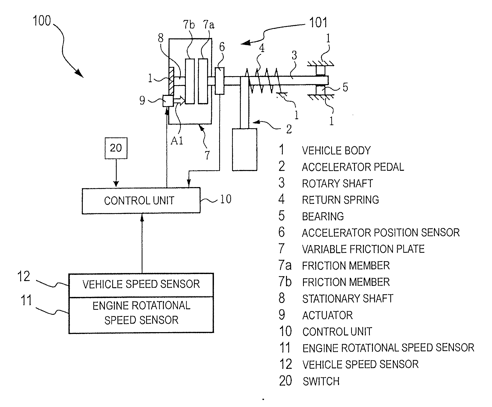
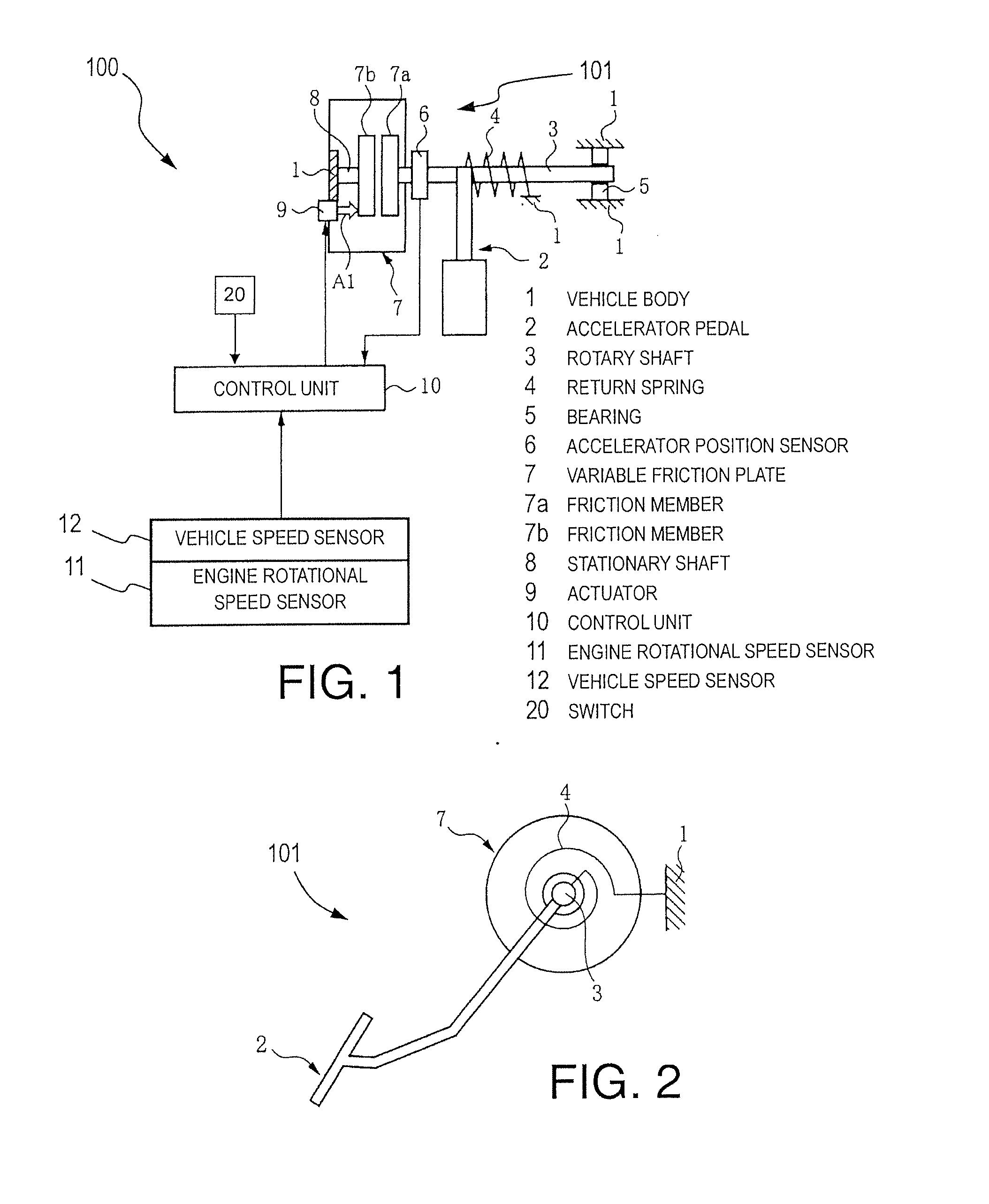
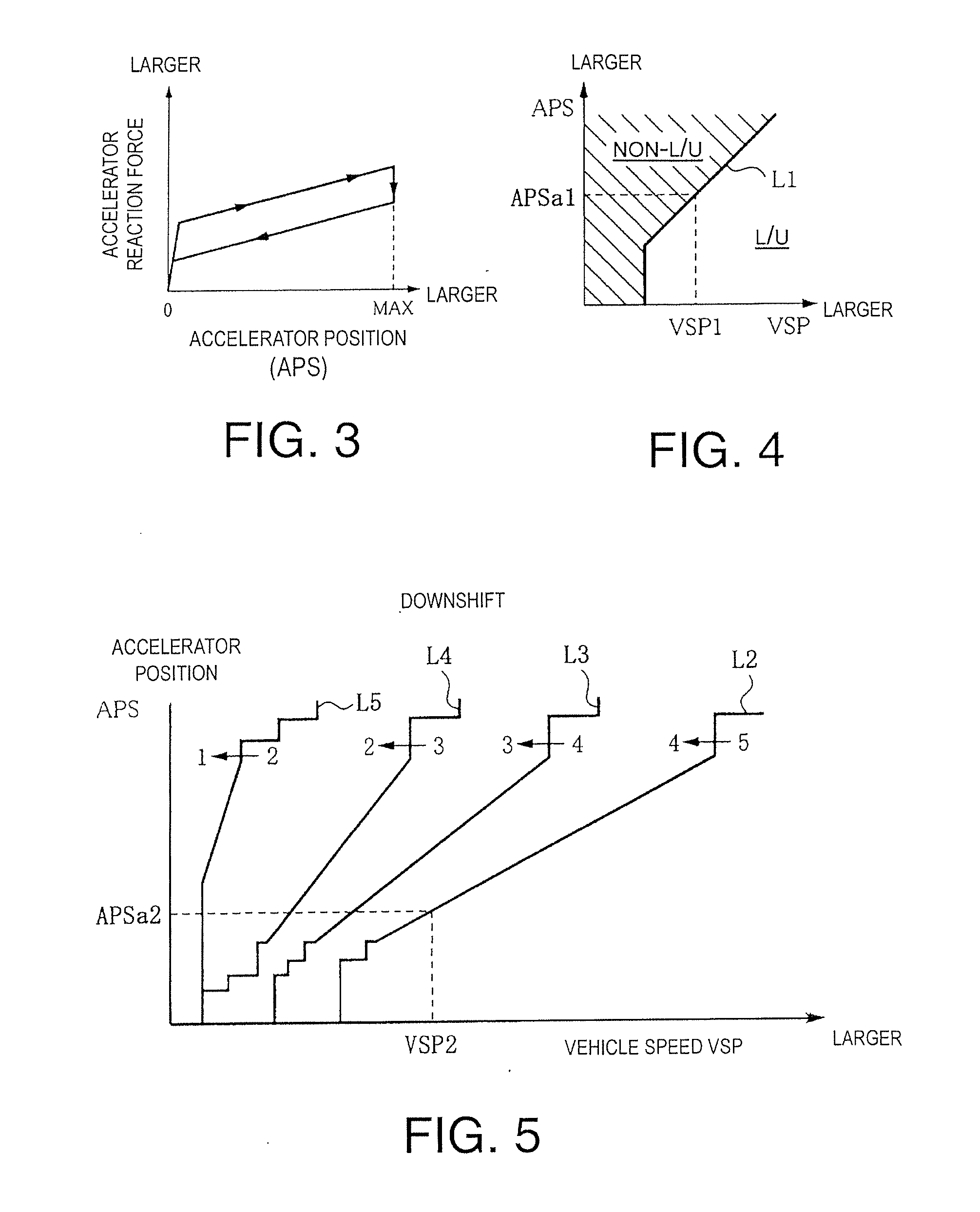
[0042]In the first embodiment, an example of a variable reaction force increase amount is one that is set to be larger when an accelerator position threshold value set based on a vehicle and / or engine operating state. Specifically, the control unit 10 of the accelerator reaction force control apparatus 100 controls the actuator 9 so as to increase a reaction force of the accelerator pedal 2 by a prescribed increase amount A beyond a base reaction force when an accelerator position becomes larger than an accelerator position threshold value. The accelerator reaction force control apparatus 100 is characterized by the control unit 10 varying an increase rate at which the reaction force of the accelerator pedal 2 is increased beyond the base reaction force such that when the reaction force is increased, an increase rate at which the reaction force is increased during a second reaction force increase period of the increase is larger than an increase rate at which the reaction force is i...

second embodiment

[0062]With the second embodiment, the apparatus can also be configured such that the amount by which the reaction force is increased when the accelerator position becomes larger than the accelerator position threshold value APSa can be selected between more than two levels (e.g., three levels including a strong, a medium, and a weak level).

[0063]In the embodiments explained heretofore, when the reaction force of the accelerator pedal 2 is increased by the prescribed increase amount A beyond the base reaction force, the rate at which the reaction force is increased with respect to the accelerator position is changed in two stages. However, it is acceptable to change the rate at which the reaction force is increased with respect to the accelerator position in multiple stages successively.

[0064]It is also acceptable to set the reaction force increase amount added to the base reaction force such that it increases, for example, according to a second degree curve with respect to an increa...


PUM


Abstract

An accelerator reaction force control apparatus is provided with an accelerator position detecting device, a reaction force varying device and a threshold value setting device. The reaction force varying device varies a reaction force of the accelerator so as to increase a reaction force of the accelerator by a prescribed increase amount with respect to a base reaction force when the accelerator position is equal to or larger than an accelerator position threshold value. The reaction force varying device also varies a reaction force increase rate at a first increase rate during a first reaction force increase period of the increase of the reaction force, and at a second increase rate during a second reaction force increase period of the increase of the reaction force. The second increase rate is larger during the second reaction force increase period than during the first reaction force increase period.

Description

CROSS-REFERENCE TO RELATED APPLICATIONS[0001]This application claims priority to Japanese Patent Application No. 2009-216758, filed on Sep. 18, 2009. The entire disclosure of Japanese Patent Application No. 2009-216758 is hereby incorporated herein by reference.BACKGROUND[0002]1. Field of the Invention[0003]The present invention generally relates to an accelerator reaction force control apparatus for controlling an operating force of an accelerator of a vehicle.[0004]2. Background Information[0005]An accelerator reaction force control apparatus have been proposed for controlling an operating force (depression reaction force) of an accelerator pedal of a vehicle. An example of such an accelerator pedal reaction force control apparatus is disclosed in Japanese Laid-Open Patent Publication No. 2003-120339. This publication discloses controlling the engine by switching between a first operating method (e.g., homogeneous combustion) used in a high rotational speed / high load region and a ...

Claims


Application Information

Patent Timeline
Patent Type & Authority Applications(United States)
IPC IPC(8): G06F7/00
CPCB60K26/021G05G1/38F02D11/02B60K2026/023B60K26/02
Inventor SAKAGUCHI, SHIGEYUKISHIOMI, MASAOOMORI, MASAHIRO
Owner NISSAN MOTOR CO LTD
Why Eureka
Try Eureka