[0008]It is an object of the invention to provide a bicycle pedal in which the position of the foot relative to the pedal is improved also for a non-fixed connection of a shoe and the pedal.
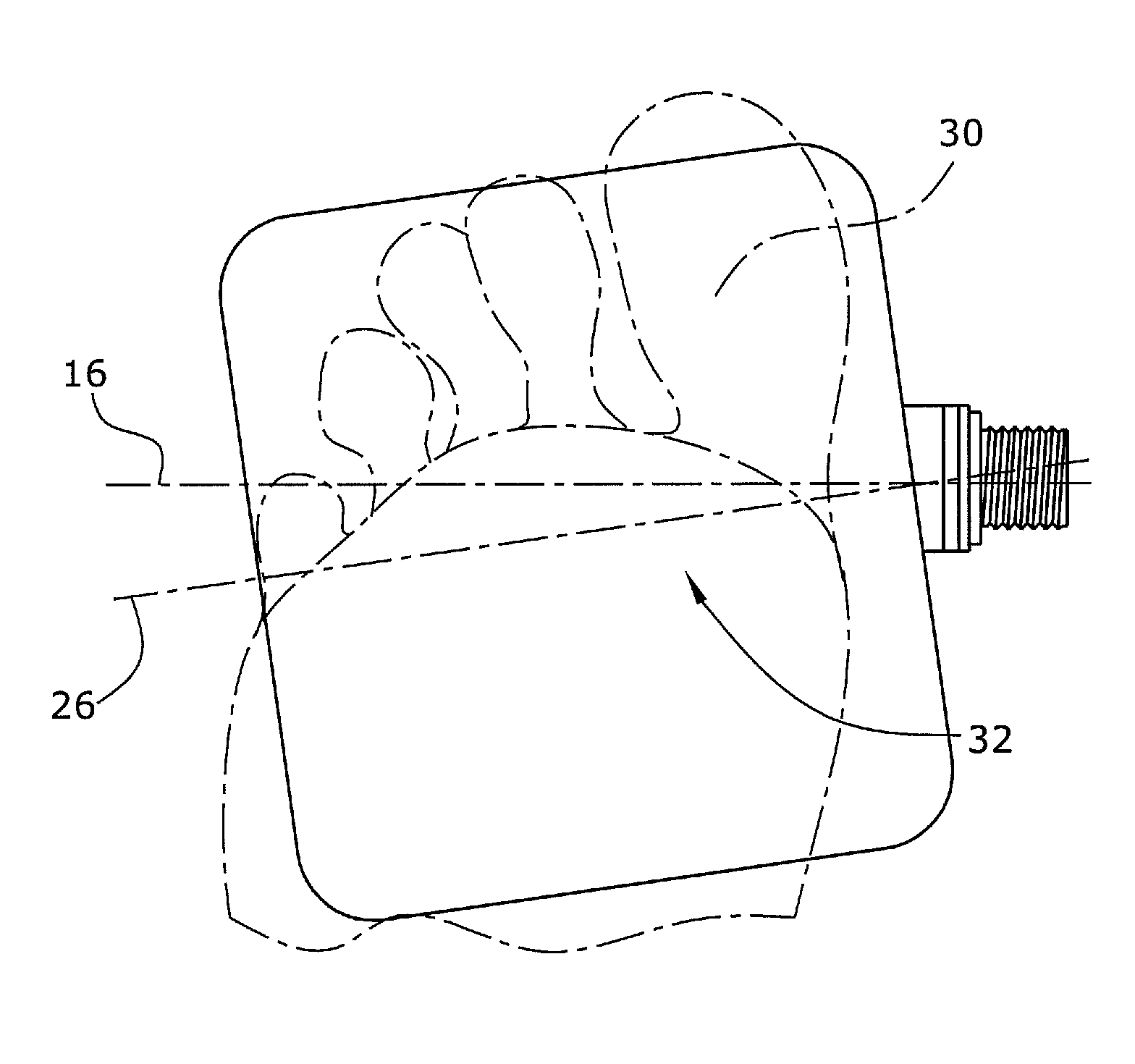
[0011]Such a recess, as provided according to the invention, has the effect that the foot of a cyclist is intuitively positioned better on the pedal. For one, there is no more pedaling using the metatarsus, since the sole of the foot or shoe no longer rests flatly on the pedal, but would touch the
support surface of the pedal only at the front and rear sides. The user intuitively pulls the foot backward, since the shoe and the foot can be bent in the region of the
toe joints so that the shoe again rests on the pedal, making full contact therewith. Thus, providing a recess, such as a depression, has the first
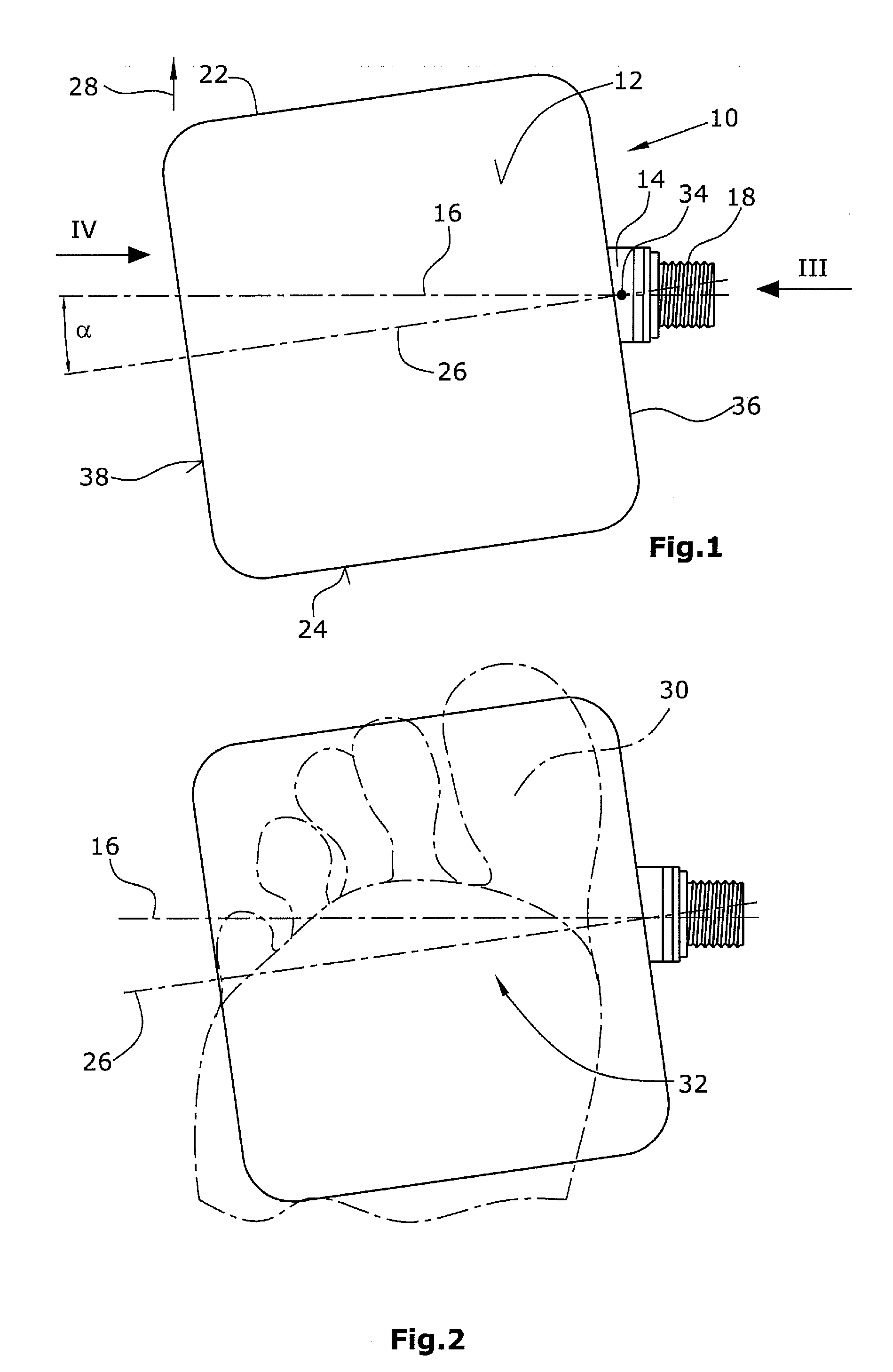
advantage that the user positions his foot on the pedal such the transmission of force is effected substantially via the ball of the foot or the metatarso-phalengeal joints, respectively. Since, according to the invention, the deepest portion of the recess is offset with respect to the pedal axle, the foot is also intuitively placed on the pedal in a manner corresponding to the offset. This results in an ergonomically better position of the foot. By arranging the deepest portion of the recess in this manner, it is prevented that the
heel of the foot is turned too far outward or inward. The ergonomically improved position of the foot on the pedal reduces the loads occurring in particular in the
ankle joint and the
knee joint, but also the loads occurring in the hip joint.
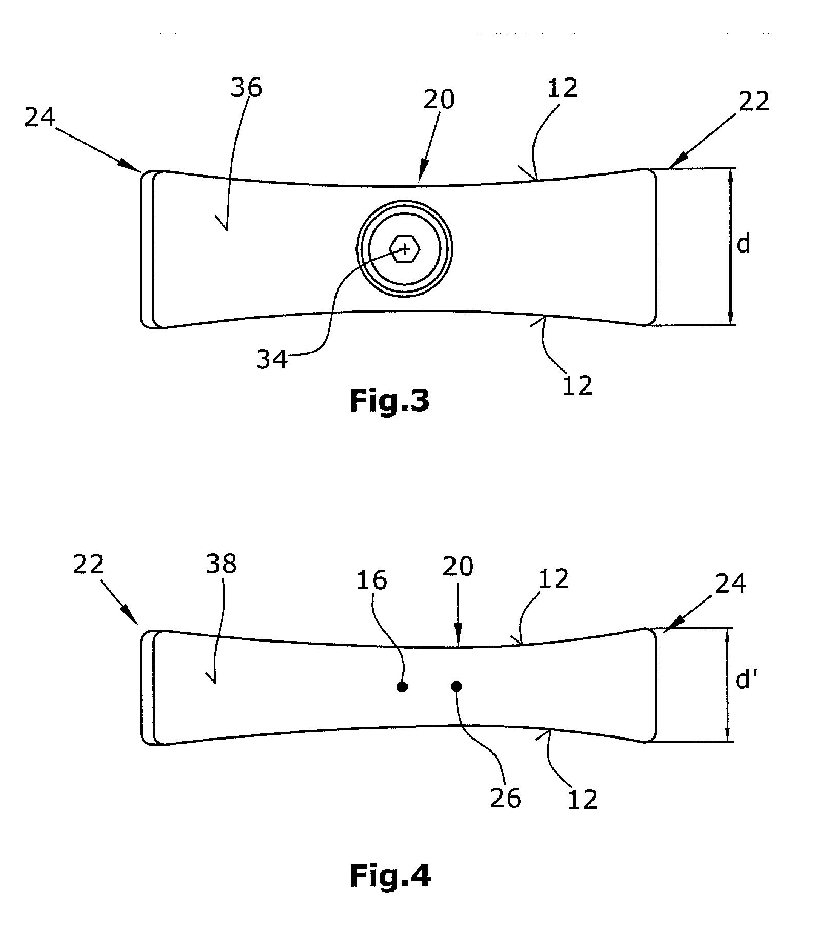
[0013]It is particularly preferred to design the recess such that it has no steps, but rather extends, in particular, in a continuous manner. This allows a smooth design of the support surface. In particular, the depth of the recess increases continuously, starting from a rear side of the support surface to the deepest portion of the recess. It is particularly preferred that the depth decreases, starting from the deepest portion of the recess to the front side of the support surface. To further improve the position of the foot and to prevent the user from placing his foot too far forward on the pedal, it is possible to make the inclination from the deepest portion of the recess to the front side of the support surface somewhat steeper or more pronounced than in the rear portion.
[0015]Preferably, the pedal of the invention is a pedal with opposite support surfaces. It is preferred that they are of the same design so that the user does not have to take care on which of the two sides he sets the foot. However, it is also possible to provide a combined pedal which is designed as a click pedal on the one side and, on the other side, as a pedal of the inventive design with a recess. Such a pedal can thus, on the one hand, be used with special shoes, e.g. with a click connection, and, on the other hand, when conventional shoes are used, such a pedal also guarantees an ergonomically favorable position of the foot, as well as a good transmission of force, when the foot is placed on the support surface designed according to the invention.
[0017]The position of the foot can be improved further, by making the support surface slanted outward, i.e. away from the
crank. With such a slight inclination, the effect of a so-called Varus wedge is achieved. This has positive effects on the position of the foot joint. The inclination at the support surface preferably is 1-3°, in particular about 1.5°, with respect to the horizontal surface.

