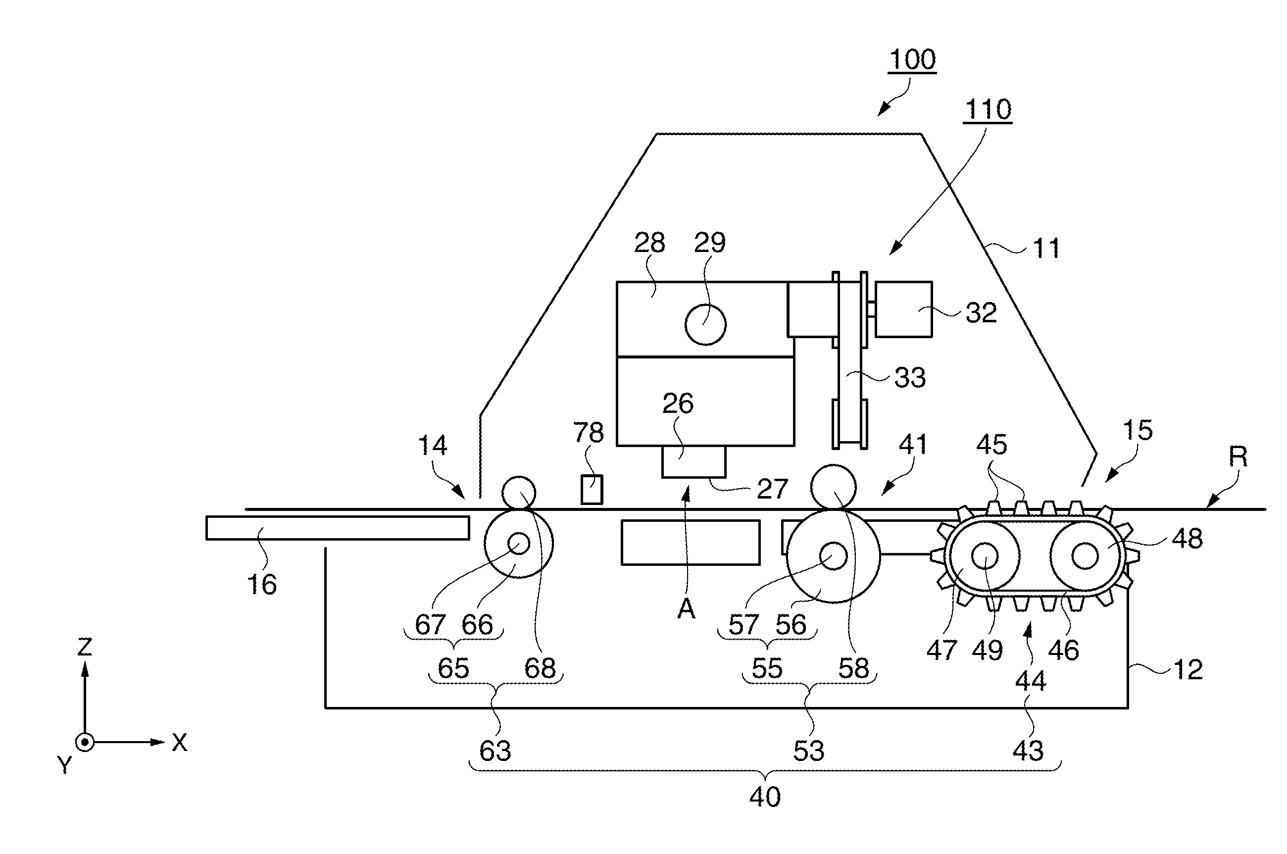
[0014]The paper conveyance device uses the first conveyance mechanism as the main conveyance mechanism. This assures the desired paper feed distance and paper feed force on the continuous paper. Each of the second and third conveyance mechanisms is configured to, in the absence of the restraint on the paper provided by the first conveyance mechanism, convey the continuous paper at a rate slightly greater than the conveyance rate of the first conveyance mechanism. Due to the positive restraint provided by the first conveyance mechanism and the ability of the paper to slip relative to the second and third conveyance mechanisms, the combination of the first, second, and third conveyance mechanisms produces tension in the continuous paper between the first conveyance mechanism and the third conveyance mechanism. The difference between the paper feed rate of the first conveyance mechanism and the paper feed rates of the second and third conveyance mechanisms is preferably small. As a result, a suitable level of tension can be applied to the conveyed continuous paper on the paper conveyance path from the first conveyance mechanism to the third conveyance mechanism including the printing position. Problems such as folds, wrinkles, or slack in the continuous paper resulting from conveyance are reduced by this tension. As a result, continuous paper can be conveyed with few folds, wrinkles, or slack.
[0015]The tractor of the first conveyance mechanism constrains the position of the conveyed continuous paper along the feed direction. In contrast, the second conveyance mechanism and the third conveyance mechanism are used to generate tension in the conveyed continuous paper and do not positively constrain the conveyed continuous paper along the feed direction because the paper can slip relative to the rollers of the second and third conveyance mechanisms. The continuous paper is therefore held by the first conveyance mechanism, and slight slipping occurs between the conveyed continuous paper and the rollers of the second and third conveyance mechanisms. As a result, continuous paper can be conveyed in the paper conveyance device at the desired paper feed amount set by the first conveyance mechanism. More specifically, continuous paper can be conveyed a reference paper feed amount while maintaining a suitable level of tension in the continuous paper. A printing device using this paper conveyance device can therefore assure the desired paper feed precision while reducing printing problems caused by folds, wrinkles, or slack in the continuous paper, and can assure good print quality.
[0016]In many embodiments, the second and third conveyance mechanisms are configured to have specific characteristics. For example, the paper feed distance per unit time of the third conveyance mechanism can be greater than the paper feed distance per unit time of the second conveyance mechanism, thereby serving to more quickly generate a suitable level of tension in the conveyed continuous paper between the second conveyance mechanism and the third conveyance mechanism. As another example, a combined maximum paper holding force of the second and third conveyance mechanisms can be set to be suitably below a maximum paper holding force of the first conveyance mechanism so that the continuous paper will slip relative to the rollers of the second and third conveyance mechanisms before the
resultant tension in the continuous paper between the first conveyance mechanism and the second conveyance mechanism exceeds a maximum paper holding force of the first conveyance mechanism. By ensuring that the continuous paper will slip relative to the rollers of the second and third conveyance mechanisms before the maximum paper holding force of the first conveyance mechanism is exceed, corresponding damage to the continuous paper (e.g., torn holes) may be prevented. And the maximum paper holding force of the third conveyance mechanism can be less that the maximum paper holding force of the second conveyance mechanism (e.g., by having the pressure of the second pressure roller on the second feed roller be less than the pressure of the first pressure roller on the first feed roller).
[0017]In addition, the
detector is used to detect the actual paper feed distance by the first conveyance mechanism and the rotation of the first feed roller of the second conveyance mechanism. And based on the detected result, the paper feed amount of the first conveyance mechanism can be adjusted. As a result, the actual paper feed distance and slipping can be monitored even in a configuration that causes slipping in the second conveyance mechanism, and the paper feed amount of the first conveyance mechanism can be adjusted when a difference to the reference paper feed amount occurs. As a result, high precision paper conveyance is possible.
[0022]With these configurations, drive power from a motor, which is a common drive power source, can be directly transferred from the motor gear through the
toothed belt to the first conveyance mechanism and second conveyance mechanism. A detector disposed to the feed roller of the second conveyance mechanism can detect the actual paper feed distance of the first conveyance mechanism and the rotation of the first feed roller of the second conveyance mechanism. The actual paper feed distance and slipping at the second conveyance mechanism can therefore be monitored. As a result, when a difference to the reference paper feed amount occurs due to variation in the load or slipping, the paper feed amount of the first conveyance mechanism can be adjusted. High precision paper conveyance can therefore be achieved.
[0024]The printing device can apply specific tension to the conveyed continuous paper, and can reduce problems such as folds, wrinkles, and slack in the continuous paper. The actual paper feed distance and slipping at the second conveyance mechanism can also be monitored, and error can be eliminated when there is a difference between the actual paper feed distance and the reference paper feed distance. The printer can therefore reduce printing problems caused by folds, wrinkles, or slack in continuous paper, can assure paper feed precision, and can achieve high print quality.

