Eureka AIR delivers breakthrough ideas for toughest innovation challenges, trusted by R&D personnel around the world.

Hydraulic chain tensioner device

A tensioner, hydraulic technology, applied in the direction of transmission, belt/chain/gear, mechanical equipment, etc., can solve the problems of large chain noise, large transmission noise, heavy gear and other problems, and achieve smooth and high promotion of sprocket transmission. Value, compact layout

Inactive Publication Date: 2012-10-17
东风朝阳朝柴动力有限公司
View PDF5 Cites 6 Cited by
  • Summary
  • Abstract
  • Description
  • Claims
  • Application Information

AI Technical Summary

Problems solved by technology

At present, the driving structure of the engine mostly adopts belt transmission and gear transmission. The noise of the belt transmission is small, but it is easy to cause the belt to slip, so that the speed of the pulley cannot rotate according to the ideal transmission ratio, thereby reducing the transmission efficiency and power of the engine.
The gears used in gear transmission are mostly helical gears, which have high machining accuracy. In addition to increasing the cost, the weight of the engine is increased due to the thicker gears, and the transmission noise is also relatively large.
In addition, at present, a certain amount of clearance must be reserved between the tensioning device of the mechanical rigid structure and the chain, and the chain will also generate relatively large noise when it is working.

Method used


Image

  • Hydraulic chain tensioner device
  • Hydraulic chain tensioner device

Examples


Embodiment Construction

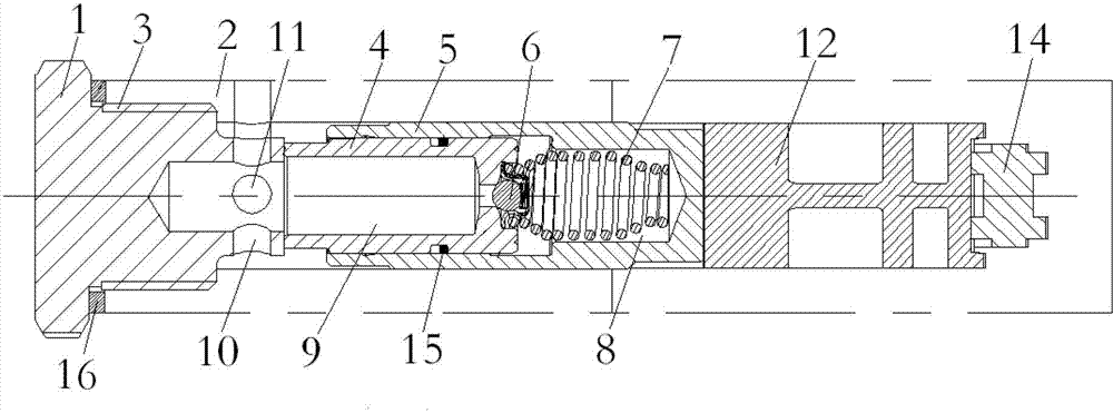
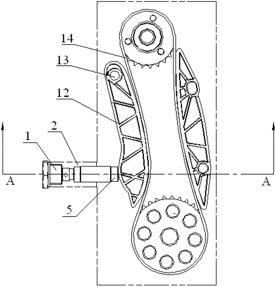
[0008] The principle and structure of the present invention will be further explained below with reference to the drawings and specific embodiments. Hydraulic chain tensioner device (such as figure 1 ), its structure is: tensioner fastening seat 1 and sprocket chamber 2 ( figure 1 The middle part) is fastened by the thread 3, and the foremost end of the tightening seat of the tensioner is close to the plunger 4, and the plunger is placed in the plunger sleeve 5. A check valve 6 and a return spring 7 are sequentially arranged between the plunger and the plunger sleeve, and the return spring is placed in the oil storage chamber 8 of the plunger sleeve. The oil cavity of the tightening seat of the tensioner is communicated with the plunger oil cavity 9, and the oil cavity of the tightening seat of the tensioner is provided with a horizontal oil passage 10 and a longitudinal oil passage 11. The guide plate 12 is in contact with the outer end of the plunger sleeve, and the guide pla...


PUM


Abstract

The invention discloses a hydraulic chain tensioner device. The structure is as follows: a tensioner fastening seat and a sprocket chamber are fastened and connected through threads, the forefront end of the tensioner fastening seat abuts against a plunger, and the plunger is arranged in a plunger bushing; a check valve and a return spring are sequentially arranged between the plunger and the plunger bushing, and the return spring is arranged in an oil storage chamber of the plunger bushing; a tensioner fastening seat oil chamber is communicated with a plunger oil chamber, and a transverse oil duct and a longitudinal oil duct are arranged in the tensioner fastening seat oil chamber; and a guide plate contacts the outer end of the plunger bushing and is fixed with the sprocket chamber through bolts, and a chain is arranged in a guide plate positioning groove. The device adopts sprocket drive, so the engine has the advantage of simple structure and compact layout. The tensioner can ensure the smooth sprocket drive, and has proper tension for the chain. The hydraulic chain drive can obviously reduce the noise. The invention is especially suitable for overhead camshaft engines, and has high popularization value.

Description

Technical field [0001] The invention belongs to engine parts, and specifically relates to a hydraulic chain tensioning component device. technical background [0002] With the continuous improvement of various aspects of the automobile industry, the power of the engine is also increasing, and the purpose of technical improvements is to improve the transmission performance of the vehicle and simplify the structure. At present, the driving structure of the engine mostly adopts belt transmission and gear transmission. The belt transmission noise is small, but it is easy to cause belt slippage, so that the pulley speed cannot rotate according to the ideal transmission ratio, thereby reducing the transmission efficiency and power of the engine. The gears used in gear transmission are mostly helical gears, which have high processing accuracy. In addition to increasing costs, the heavy gears increase the weight of the engine, and at the same time, the transmission noise is also relative...

Claims


Application Information

Patent Timeline
Patent Type & Authority Applications(China)
IPC IPC(8): F16H7/08
Inventor 陈玉荣李晓刚张宏辉赵霄鹏张学存李长水乌永波张俊波蔡旭冰
Owner 东风朝阳朝柴动力有限公司
Why Eureka
Eureka Blog
Learn More