
Display device with improved display performance

Active Publication Date: 2012-03-15
E INK HLDG INC
View PDF0 Cites 2 Cited by
  • Summary
  • Abstract
  • Description
  • Claims
  • Application Information

AI Technical Summary

Benefits of technology

[0007]The present invention relates to display device that can avoid occurring crosstalk phenomena and improve display performance without influencing a resolution and a response speed.
[0009]In the display device of the present invention, because the dielectric constant of the partition walls is less than that of the dielectric solvent, when the predetermined display units are driven, the capacitance value induced at the partition walls by the driving voltage can be decreased. Thus, the crosstalk phenomena can be avoided in the display units that are not driven. As such, the display performance of the display device can be improved without influencing the resolution and the response speed.

Problems solved by technology

As such, the charged particles of the microcup display units that are not required to drive would move improperly.
Consequently, grey scale is prone to changing improperly and images are prone to distortion, and thus display performance of the microcup electrophoretic display device may be degraded.
However, a resolution of the microcup electrophoretic display device would be degraded with increasing the distance between adjacent microcup display units.

Method used


Image

  • Display device with improved display performance
  • Display device with improved display performance
  • Display device with improved display performance

Examples


Embodiment Construction

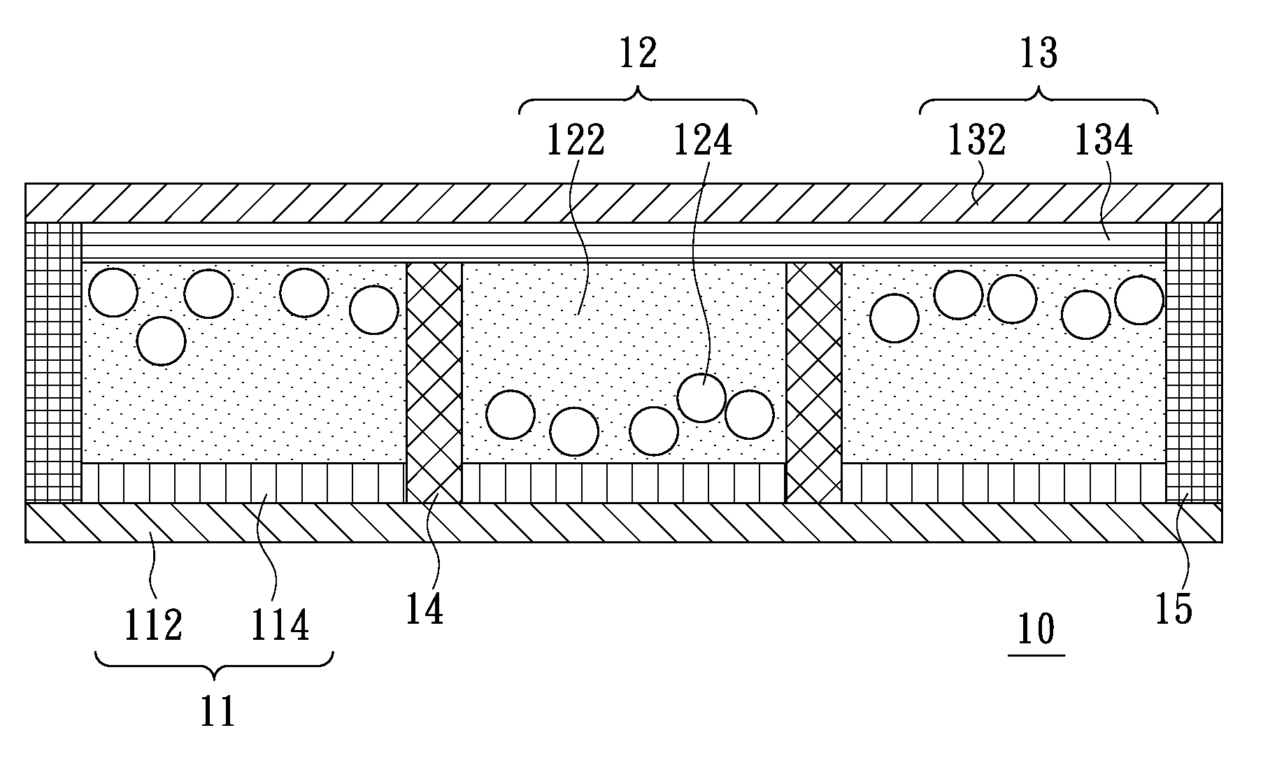
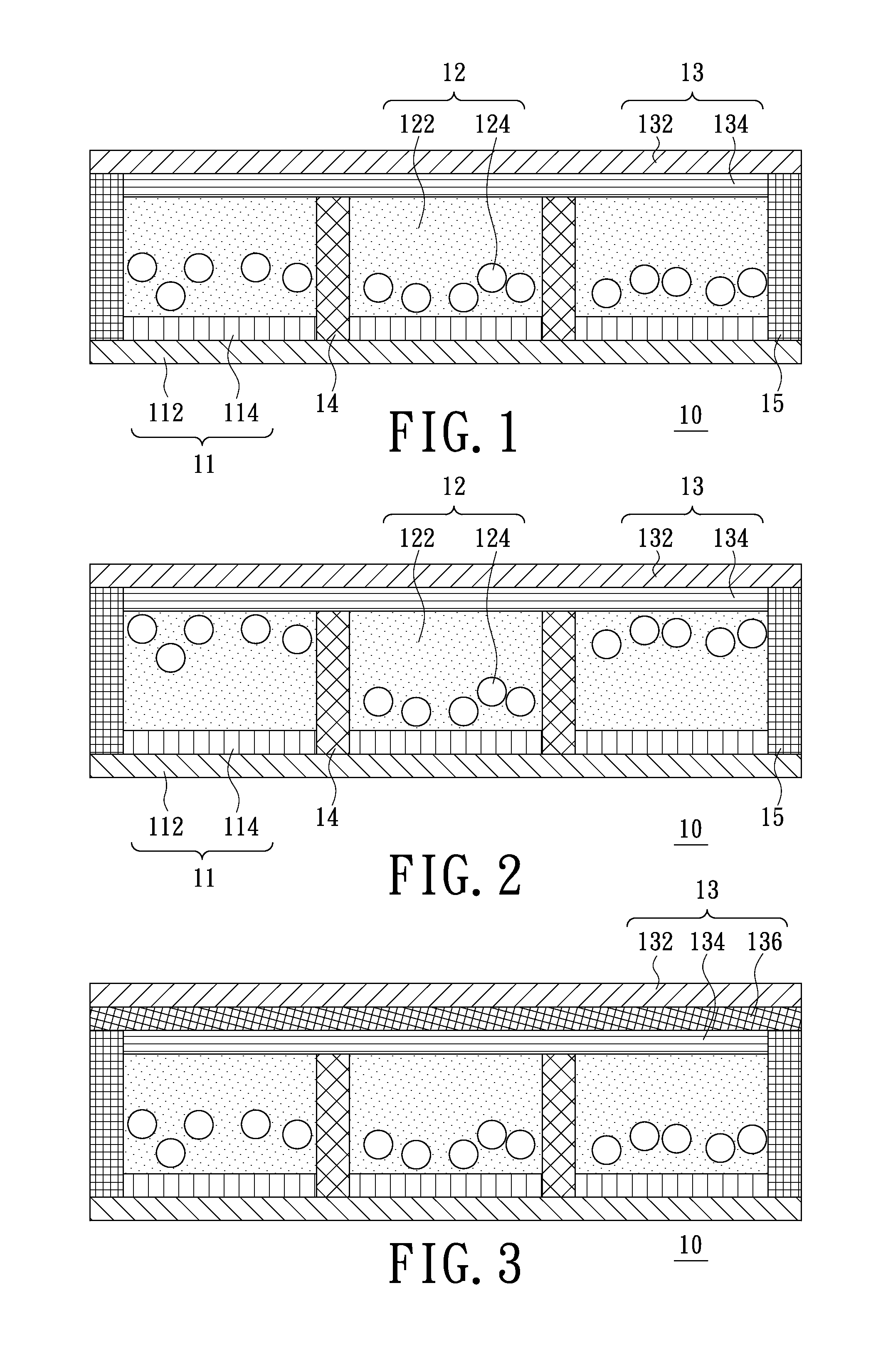
[0014]FIG. 1 is a schematic cross-sectional view of a display device according to an exemplary embodiment of the present invention. Referring to FIG. 1, the display device 10 is a microcup electrophoretic display (EPD) device for exemplary purposes, but may be other display devices, such as a quick response-liquid powder display (QR-LPD) device and an electro-wetting display (EWD) device. The display device 10 includes a first substrate 11, a plurality of display units 12, a second substrate 13 and a plurality of partitioning walls 14. The second substrate 13 is disposed above the first substrate 11. The display units 12 are disposed between the first substrate 11 and the second substrate 13, and each of the display units 12 has a dielectric solvent 122. The partitioning walls 14 are disposed between adjacent display units 12 correspondingly, and a dielectric constant of each of the partitioning walls 14 is less than that of the dielectric solvent 122 adjacent thereto. In the embodi...


PUM


Abstract

A display device includes a first substrate, a second substrate, a plurality of display units and a plurality of partitioning walls. The second substrate is disposed above the first substrate. The display units are disposed between the first substrate and the second substrate, and each of the display units has a dielectric solvent. The partitioning walls are disposed between adjacent display units correspondingly, and a dielectric constant of each of the partitioning walls is less than that of the dielectric solvent adjacent thereto. Because the dielectric constant of the partition walls is less than that of the dielectric solvent adjacent to the partition wall, a capacitance value induced at the partition wall by a driving voltage can be decreased. Thus, crosstalk phenomena can be avoided in the display unit that is not driven.

Description

BACKGROUND[0001]This application is a continuation-in-part (CIP) of U.S. application Ser. No. 12 / 436,288 filed on May 08, 2009, which claims the benefit of priority to Taiwan application No. 098113049 filed Apr. 20, 2009. The entire disclosure of U.S. application Ser. No. 12 / 436,288 is incorporated herein by reference.FIELD OF THE INVENTION[0002]The present invention relates to a display device, and more particularly to a display device with improved display performanceDESCRIPTION OF THE RELATED ART[0003]In these days, with the development of science and technology, display devices have been used more and more widely in various electronic products. Furthermore, with light, thin, short, small and portable trend of development of the electronic products, some flexible displays devices that are thin in thickness and flexible appear in the market, such as, a microcup electrophoretic display (EPD) device, a quick response-liquid powder display (QR-LPD) device and an electro-wetting displ...

Claims


Application Information

Patent Timeline
IPC IPC(8): G02F1/167G02B26/00
CPCG02F1/167G02F2202/42G02F2001/1672G02F1/1681
Inventor WANG, TZU-MINGCHEN, LEE-TYNGSHINN, TED-HONG
Owner E INK HLDG INC
Learn More