Path analyzer

a path analyzer and path technology, applied in the field of path analyzers, can solve problems such as packet loss, quality degradation failure, and sometimes increased communication delay, and achieve the effects of increasing communication delay, reducing quality, and reducing the number of path analyzers

Inactive Publication Date: 2012-03-15
FUJITSU LTD
View PDF1 Cites 9 Cited by
  • Summary
  • Abstract
  • Description
  • Claims
  • Application Information

AI Technical Summary

Benefits of technology

[0008]The object and advantage of the invention will be realized and attained by means of the elements and combinations particularly pointed out in the claims.
[0009]It is to be understood that both the foregoing general description and the following detailed description are exemplary and explanatory and are not restrictive of the invention, as claimed.

Problems solved by technology

In IP networks, quality deterioration failures such as disruption, packet loss, or increased communication delay sometimes occur due to setting errors or faults of a relay device (relay node) between terminals.

Method used


Image

  • Path analyzer
  • Path analyzer
  • Path analyzer

Examples


first embodiment

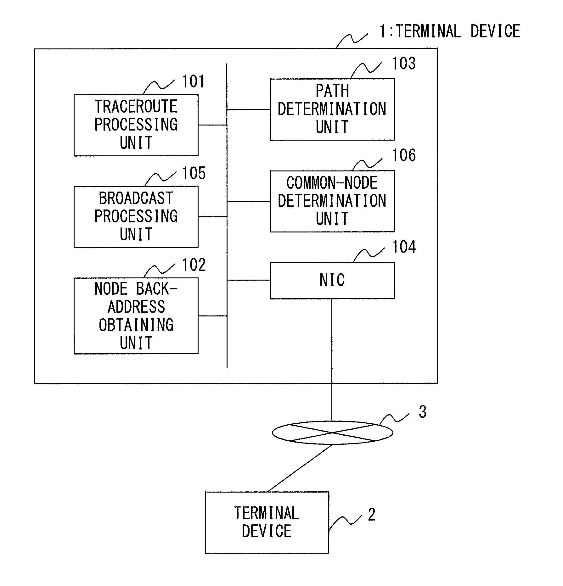
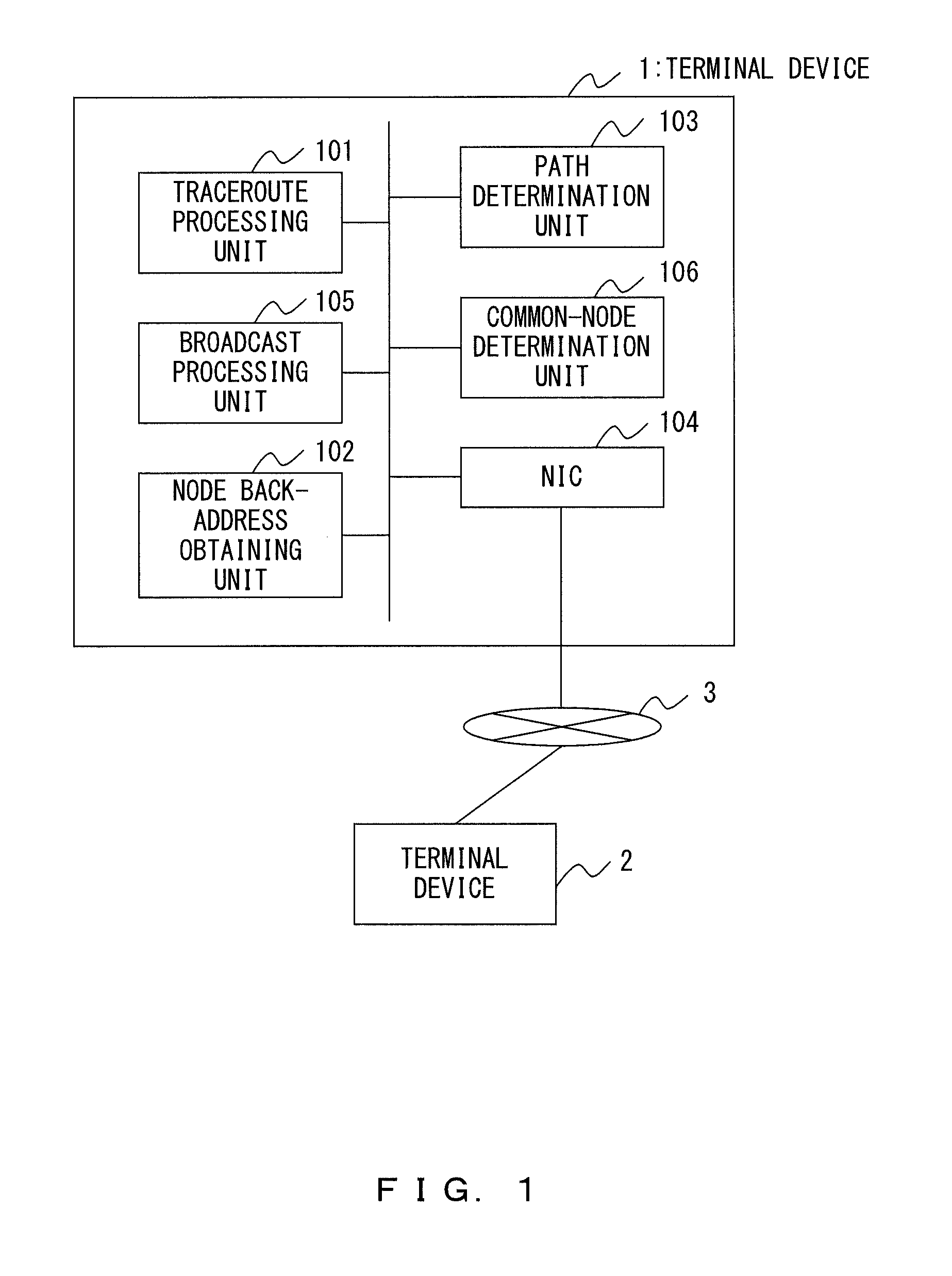
[0041]The first embodiments of the present invention will be described in detail. FIG. 1 is a block diagram illustrating a schematic configuration of a terminal device according to the first embodiment. FIG. 1 only illustrates primary functional blocks that relate to the path analysis from among the functions of a terminal device, and the illustration and explanation of known functions of a terminal device will be omitted. In other words, an actual terminal device may involve various functions other than the ones illustrated in FIG. 1. In the first embodiment, an example configuration is described in which a terminal device 1 functions also as a path analyzer. It is to be noted that a system may be configured such that all the terminal devices on the network have the same configuration as the terminal device 1 to execute the same operations, but it is not always necessary for all the terminal devices to have the functions of a path analyzer. Alternatively, it is also a possible conf...

second embodiment

[0074]In the second embodiment, a path analysis system capable of quickly obtaining path information when there is quality deterioration in the network will be described. The same reference signs as in the first embodiment will be given to the elements that have a similar function as that of the first embodiment, and detailed descriptions of them will be omitted. Although an IP telephone network is described as an example in the present embodiment, application to the path analysis in server-client systems is also possible.

[0075]As illustrated in FIG. 6, a path analysis system according to the present embodiment comprises IP telephone terminals as the terminal devices 1 and 2 , wherein each terminal is further provided with at least a packet loss detection unit 115 and a loss occurrence point specifying unit 116. A path analysis system according to the present embodiment is different from that of the first embodiment in the points above. Moreover, an IP telephone network 3 is connect...

third embodiment

[0082]The third embodiment according to the present invention will be described below. The same reference signs as in the first or second embodiment will be given to the elements that have a similar function as that of the first or second embodiment, and detailed descriptions of them will be omitted.

[0083]In the present embodiment, after the front address and back address of a relay node are determined as described with reference to the first embodiment, a failed portion such as one having delay failure, disruption, or packet loss is determined by using the determined address information. For this reason, a path analysis system according to the present embodiment is different from the first embodiment in that is comprises a failed section detection unit 121, as illustrated in FIG. 8. It is to be noted that the path determination unit 103, which is mentioned above with reference to the first embodiment, is not included in the example of FIG. 8. In other words, in the configuration of...


PUM


Abstract

A path analyzer to obtain an address of a relay node on a path between a first terminal device and a second terminal device includes: a first address obtaining unit to issue a command requiring a response from the first terminal device to the second terminal device and to obtain as a first address an address of a first terminal device side in the relay node on the path; a broadcast processing unit to search a candidate address for a broadcast address from the relay node according to the first address obtained and to issue a command requiring a response from the first terminal device to the candidate address; and a second address obtaining unit to obtain as a second address an address of a second terminal device side in the relay node on the path according to a response to the command issued by the broadcast processing unit.

Description

CROSS-REFERENCE TO RELATED APPLICATION[0001]This application is a continuation application of International PCT Application No. PCT / JP2009 / 055305, which was filed on Mar. 18, 2009, the entire contents of which are incorporated herein by reference.FIELD[0002]The embodiments discussed herein are related to a path analyzer that obtains a relay path between terminals in the IP network.BACKGROUND[0003]Conventionally, IP networks using an internet protocol have become widespread, and IP telephones have also been realized. In IP networks, quality deterioration failures such as disruption, packet loss, or increased communication delay sometimes occur due to setting errors or faults of a relay device (relay node) between terminals. In IP networks, generally, what relay node the communication path between terminals goes through is dynamically determined. In order to instantly specify and recover the failed portion when a failure occurs as described above, it is preferable for a network admini...

Claims


Application Information

Patent Timeline
Patent Type & Authority Applications(United States)
IPC IPC(8): H04L12/26H04L12/24H04L12/70H04L12/701
CPCH04L12/18H04L12/1863H04L45/26H04L41/0677H04L43/10H04L12/24H04L41/00
Inventor MIYAZAKI, HIDEAKI
Owner FUJITSU LTD
Why Eureka
Try Eureka