Connection structure and connection method of wiring board

a technology of connecting structure and connection method, which is applied in the direction of printed circuit aspects, printing, electrical apparatus construction details, etc., can solve the problems of insufficient and insufficient connection strength, so as to enhance the connection strength between the to-be-connected body and the wiring board

Active Publication Date: 2012-03-22
BROTHER KOGYO KK
View PDF6 Cites 6 Cited by
  • Summary
  • Abstract
  • Description
  • Claims
  • Application Information

AI Technical Summary

Benefits of technology

[0010]It is therefore an object of the invention to provide a connection structure and a connection method of the wiring board in which the connection strength between the to-be-connected body and the wiring board is enhanced.

Problems solved by technology

In the connection structure wherein the to-be-connected body and the wiring board are connected merely by the electrically conductive resin for electrical conduction between the electric contacts of the to-be-connected body and the board-side contacts of the wiring board, the connection strength between the to-be-connected body and the wiring board is insufficient, as compared with the arrangement in which the to-be-connected body and the wiring board are connected using the solders.
It is, however, revealed that such an arrangement does not ensure enough connection strength between the to-be-connected body and the wiring board.

Method used


Image

  • Connection structure and connection method of wiring board
  • Connection structure and connection method of wiring board
  • Connection structure and connection method of wiring board

Examples


Embodiment Construction

[0029]There will be hereinafter described one embodiment of the invention with reference to the drawings. In the present embodiment, the invention is applied to an ink-jet printer having an ink-jet head for jetting ink to a recording sheet.

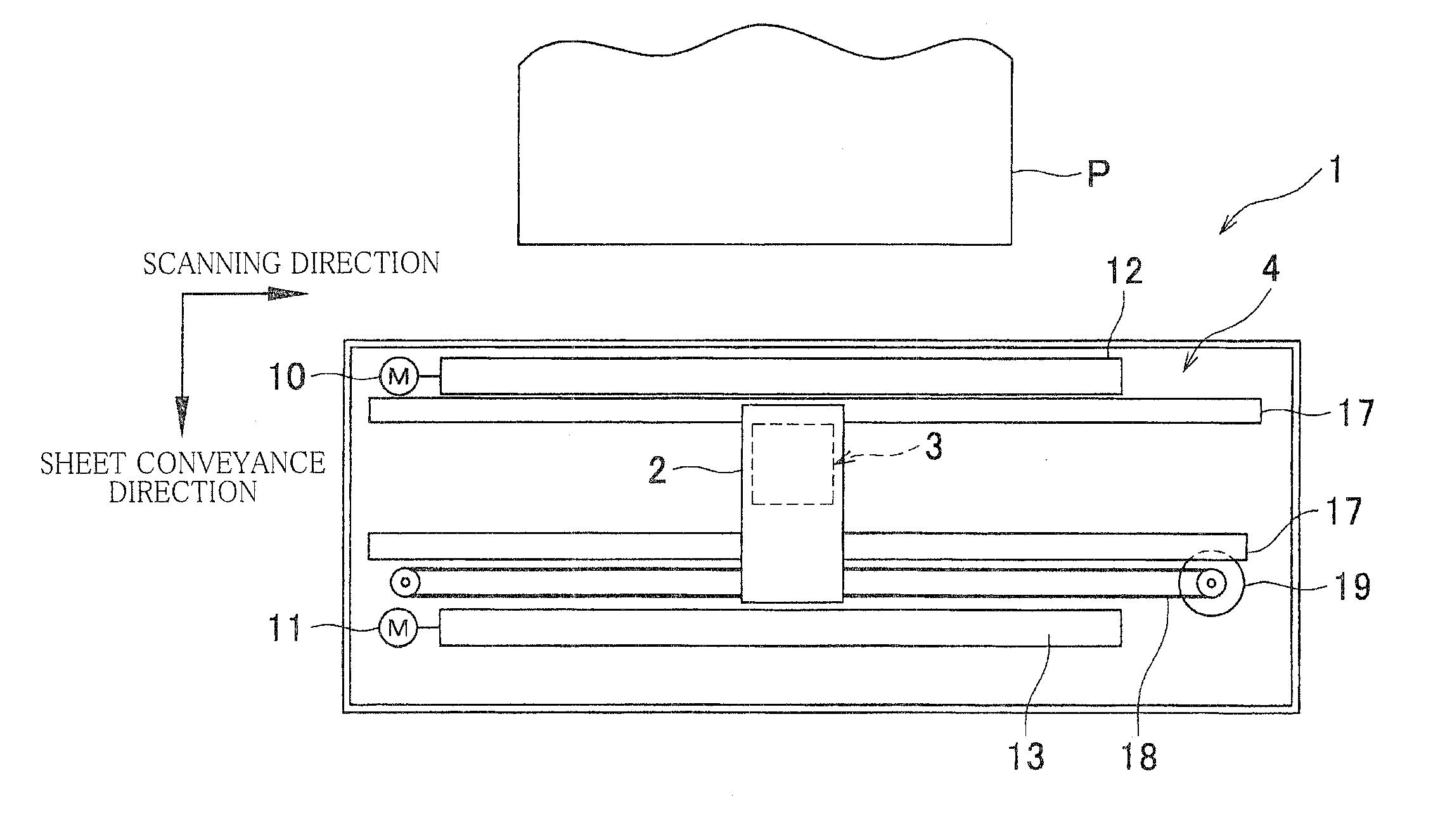
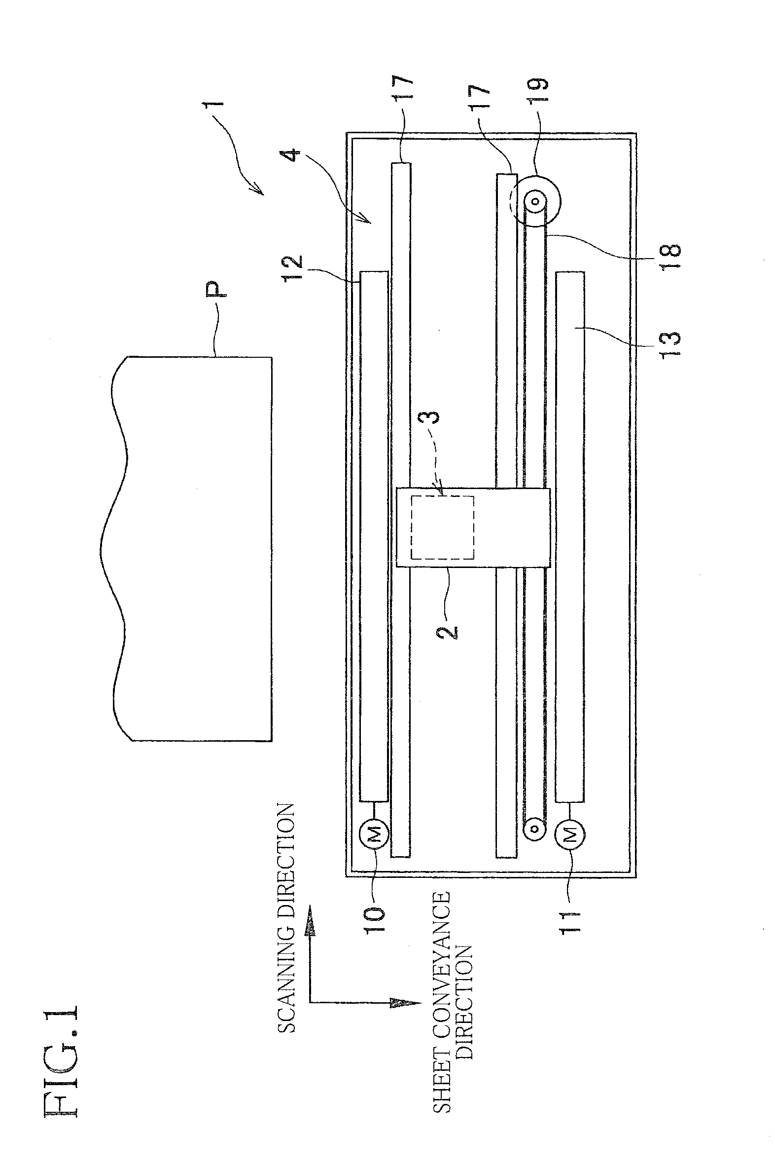
[0030]Referring first to FIG. 1, there will be first explained a structure of a printer 1 of the present embodiment. The printer 1 includes a carriage 2 configured to reciprocate in a scanning direction, namely, a left-right direction in FIG. 1, an ink-jet head 3 mounted on the carriage 2, and a conveyor mechanism 4 configured to convey a recording sheet P in a sheet conveyance or transfer direction orthogonal to the scanning direction.

[0031]The carriage 2 is configured to reciprocate along two guide shafts 17 extending parallel with the scanning direction. To the carriage 2, an endless belt 18 is connected. When the endless belt 18 is driven by a carriage drive motor 19 to move, the carriage 2 moves in the scanning direction in accordance with th...


PUM

PropertyMeasurementUnit
thicknessaaaaaaaaaa
flexibleaaaaaaaaaa
electrically conductiveaaaaaaaaaa

Abstract

A connection structure for connecting a wiring board to a to-be-connected body having electric contacts, the wiring board including: a base having board-side contacts provided on its facing surface that is to face the to-be-connected body; and a cover film which covers the facing surface except the board-side contacts and a non-covered partial region of the facing surface, the connection structure including: conduction portions formed of electrically conductive resin, for bonding the electric contacts and the board-side contacts to permit electrical conduction therebetween; and a reinforcement portion formed of the same resin as the conduction portions and disposed at a position which is different from positions of the conductive portions and at which the reinforcement portion extends across both of a surface of the cover film and a surface of the non-covered partial region of the base, the reinforcement portion bonding the to-be-connected body and the wiring board for reinforcing connection therebetween.

Description

CROSS REFERENCE TO RELATED APPLICATION[0001]The present application claims priority from Japanese Patent Application No. 2010-210420, which was filed on Sep. 21, 2010, the disclosure of which is herein incorporated by reference in its entirety.BACKGROUND OF THE INVENTION[0002]1. Field of the Invention[0003]The present invention relates to a connection structure and a connection method of a wiring board.[0004]2. Discussion of Related Art[0005]There is known a connection structure in which a wiring board is connected to a to-be-connected body, such as an actuator and a sensor, having electric contacts. In the structure, there are conducted, via the wiring board, signal transmission / reception to / from the to-be-connected body, supplying of electric power to the to-be-connected body, and so on. As one example of the connection structure between the to-be-connected body and the wiring board, there is known a connection structure between an FPC (as the wiring board) and a piezoelectric act...

Claims


Application Information

Patent Timeline
Patent Type & Authority Applications(United States)
IPC IPC(8): H05K1/00H05K3/00
CPCH05K3/321H05K3/361H05K2201/09781Y10T29/49147B41J2/04541B41J2/0458B41J2/14072H05K2201/2009
Inventor KUBO, TOMOYUKISHINKAI, YUJI
Owner BROTHER KOGYO KK
Why Eureka
Try Eureka