
Suspension device

a suspension device and suspension technology, applied in the direction of curtain suspension devices, curtain accessories, fastening means, etc., can solve the problems of reducing the holding power of the suspender, the stickiness of the glue, and the support power is too small to hold the heavier weight, etc., to facilitate the disassembly and disassembly of the suspension substrate, and the use life of the suspension substrate is long.

Inactive Publication Date: 2012-03-22
JINLIYI IND
View PDF38 Cites 18 Cited by
  • Summary
  • Abstract
  • Description
  • Claims
  • Application Information

AI Technical Summary

Benefits of technology

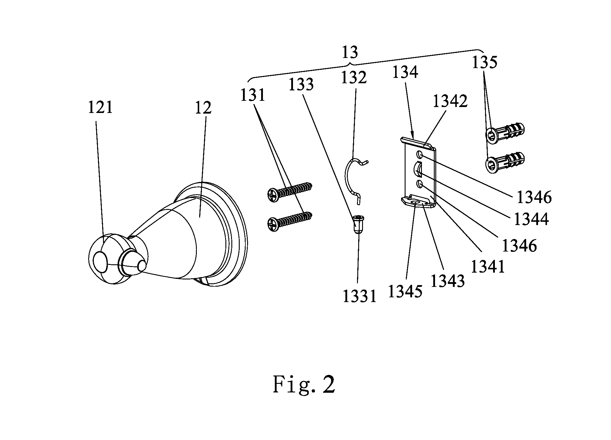
[0007]In comparison with the prior art, the suspension device of the present invention discloses that the suspension housing is hung on the wall by employing screws into the wall, concretely, the positioning assembly of the suspension device includes an elastic member and a button, when assembling the suspension device, one end of the elastic member is fixed on the suspension substrate, the other end of the elastic member is snapped into the button, and the suspension substrate is mounted on the suspension housing via the first locking arm, meanwhile, the button is successively gone through the second locking arm and the suspension housing to exposed outside, then the assembly is done. When disassembling the suspension device, the button is pushed to go through the suspension housing and the second locking arm successively to arranged within the suspension housing, then the suspension housing is facilitate to disassemble from the suspension substrate. When the user needs to change suspenders with different shapes, the previous suspender could be facilitated disassembling, and the new suspender could be mounted on the suspension substrate via the suspension housing. The suspension device of the present invention is mounted on the wall by employing the wall-in screw, so that the holding power of the suspension device is large, and the using life thereof is long. Moreover, match usage of the elastic member and the button enables the structure of the suspension device is simple, and facilitates assembling and disassembling. Preferably, according to the requirement of the user, the suspension device could change different suspenders without disassembling the suspension substrate, so the suspension device is characteristic of convenience and wider applicability.
[0008]Preferably, a fastener is arranged on and projected over the suspension substrate of the suspension device, and the upper end of the elastic member is fixed to connect to the fastener. The match usage of the fastener, the elastic member and the button facilitates the assembly and disassembly of the suspension device, so that the suspension device is characteristic of wider applicability and large holding power.
[0009]Preferably, the suspension device further comprises plugs, the wall-in screws are gone through the suspension substrate, to engage with the plugs. When the wall is cement wall, if the screw or the bolt is pounded into the cement wall directly, the suspension device is not fixed enough, hence, the plug is disclosed in the embodiment of the present invention, firstly the plug is pounded into the wall, then the wall-in screw is put into the plug so that the suspension device is fixed on the wall, long time usage and reliability of the suspension device is obtain according to this kind of fixing method.
[0014]Preferably, according to the second embodiment of the present invention, the suspender comprises an outside tube, an inner tube and a spring, two ends of the outside tube are respectively engaged with the connection holes of the connection heads, the spring and the inner tube are held within the outside tube, one end of the spring is engaged with the connection hole, the other end of the spring is engaged with one end of the inner tube, the other end of the inner tube is engaged with the connection hole. According to this embodiment, the arrangement of this suspension device enables the suspension device configured to hang up tissue, and the arrangement of the inner tube and the outside tube facilitate the change of the tissue.

Problems solved by technology

However, it exists a insurmountable problem, which is as the suspender hanging the goods for a long time, the stickiness of the glue is weaker, and the holding power of the suspender is decreased, after a period of time, though the suspender could hang light goods, e.g. accessories, nevertheless, the supporting power is too small to hold the heavier good, e.g. coat or photo frame etc, and the suspender is probable to divorced from wall to result in accident when the suspender is hang up for a long time.
Moreover, as people have larger and larger requirement as for the function of the suspender, people hope that one suspender has more functions, that is the suspender is not only the hook shape convenient for hanging clothes, but also the ring shape or rod shape convenient for hanging towel or other goods, hence, although the above suspender is characteristic of large holding power, it still could not meet the need of more functions as for people, and could not facilitate assembly and disassembly.

Method used


Image

  • Suspension device
  • Suspension device
  • Suspension device

Examples


first embodiment

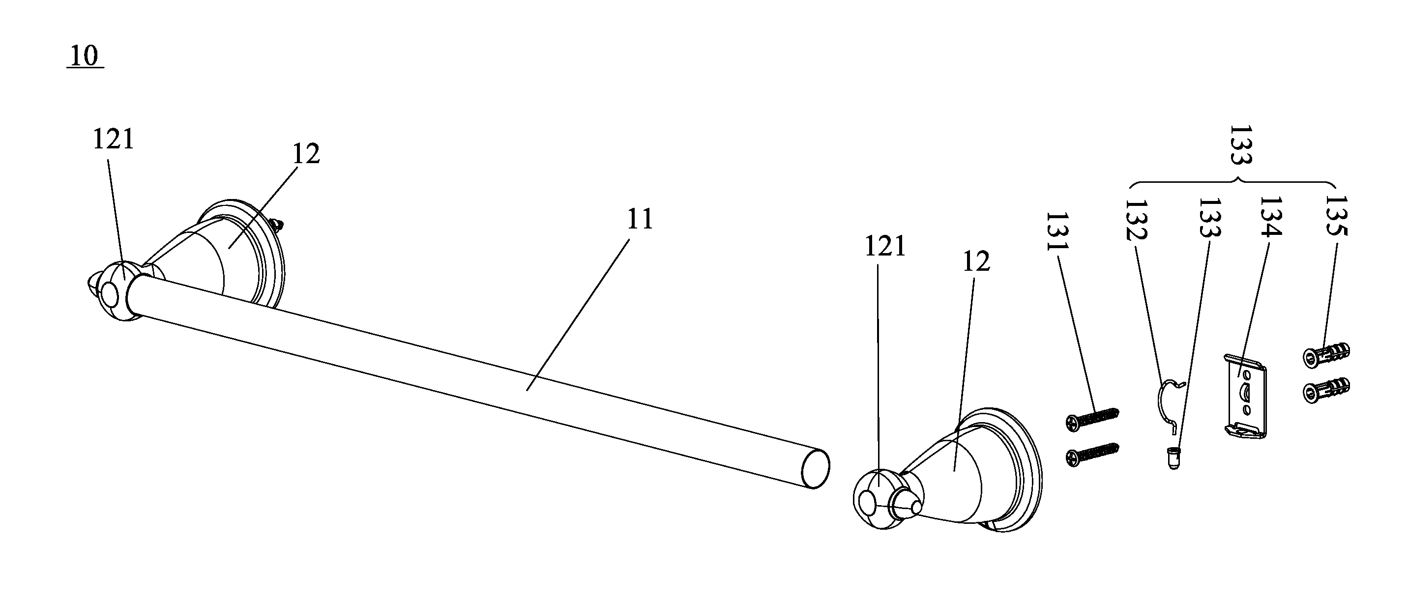
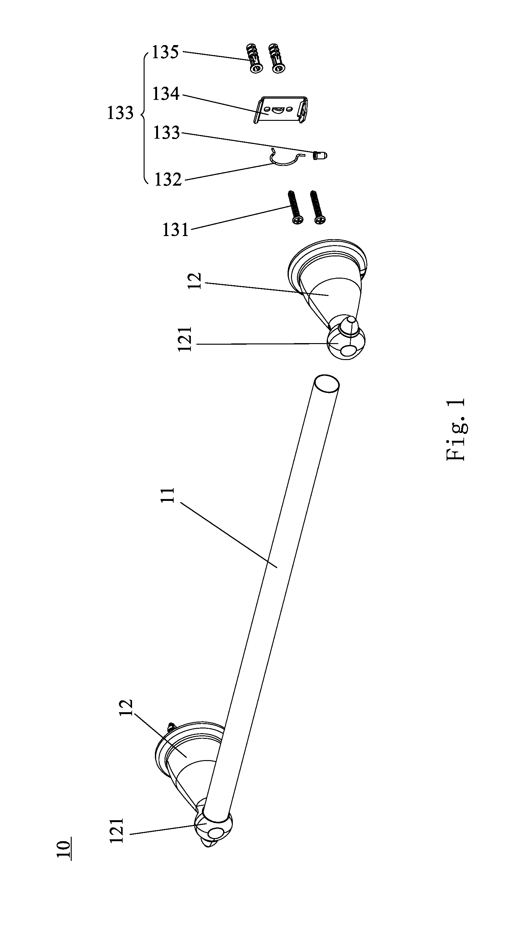
[0029]FIG. 1 is a schematic illustration demonstrating the suspension device according to the present invention. Referring to FIGS. 1-3c, the suspension device 10 includes a suspender 11, a suspension housing 12 and a positioning assembly 13, the positioning assembly 13 includes wall-in screws 131, an elastic member 132, a button 133, a suspension substrate 134 and a plug 135. The suspender 11 is mounted on the suspension housing 12. The suspension substrate 134 includes suspension substrate body 1341, and two ends of the suspension substrate body 1341 are respectively extended to form a first locking arm 1342 and a second locking arm 1343. A fastener 1344 is arranged on and projected over the suspension substrate body 1341, as a arch bridge, the fastener 1344 is formed on the suspension substrate body 1341, and arranged between the first locking arm 1342 and the second locking arm 1343. A assemble bore 1345 is formed on the second locking arm 1343, an assemble bore 1345 is a throug...

third embodiment

[0033]FIGS. 5a-5b demonstrate the suspension device according to the present invention. Referring to FIGS. 5a-5b, the suspension device 30 includes a suspender 31, a suspension housing 32 and a positioning assembly 33. According to this embodiment, the suspender 31 includes a slinger 311 and two connectors 312, and the slinger 311 is detachably mounted on the connection head 321 through the connectors 312. According to this embodiment, the arrangement of slinger enables the suspension device configured to hang up hand towel or the like. In conjugation with FIGS. 1-3c, the structure of the positioning assembly 33 of the suspension device 30 is similar to that of the positioning assembly 13, and the connection head 321 is equipped with two connection holes 322 which is different from that of the suspension device 10, and the slinger 311 is engaged with the connection holes 322 of the connection head 321 through the connectors 312 detachably. According to this embodiment, the arrangeme...


PUM


Abstract

A suspension device includes a suspender, a suspension housing, and a positioning assembly, the suspender being mounted on the suspension housing, the positioning assembly including a suspension substrate, an elastic member, a button and wall-in screws, a first locking arm and a second locking arm being respectively extended from two ends of the suspension substrate, an assemble bore being formed on the second locking arm, a blind hole being formed on the button, the upper end of the elastic member being coupled to the suspension substrate and being arranged between the first locking arm and the second locking arm, the lower end of the elastic member being snapped into the blind hole, a socket and a through hole being formed on the suspension housing, the first locking arm being engaged with the socket, the button being successively gone through the assemble bore and the through hole.

Description

FIELD OF THE INVENTION[0001]The present invention relates to a suspension device, more particularly, to a suspension device characteristic of simple structure, large holding power, facilitated assembling and disassembling.BACKGROUND OF THE INVENTION[0002]In daily life, people usually hang the living goods on the wall, e.g. hanging the towel beside the washbasin; hanging the clothes and the accessories beside the wardrobe; hang the photo frame and decorative painting, etc around the wall in the room.[0003]Diverse suspenders exist in the market currently, and people usually use one kind of suspender to hang up the living goods, this suspender could be fixed on the wall as long as it is pasted with one glue layer. Although the suspender structure is simple, it could achieve rapid assembling and facilitate using. However, it exists a insurmountable problem, which is as the suspender hanging the goods for a long time, the stickiness of the glue is weaker, and the holding power of the sus...

Claims


Application Information

Patent Timeline
IPC IPC(8): F16M13/02
CPCA47K10/10F16B21/125F16B9/023A47K2201/02
Inventor HE, GUODONGLONG, YUNYOUYANG, GUOFENG
Owner JINLIYI IND
Learn More