Grinding type vertical grain milling machine

Active Publication Date: 2012-03-22
SATAKE CORP
View PDF8 Cites 23 Cited by
  • Summary
  • Abstract
  • Description
  • Claims
  • Application Information

AI Technical Summary

Benefits of technology

[0027]According to the invention described in claim 4, since there are provided the inner peripheral edge protruding toward the lower portion of the rim portion of the fan-pulley, the outer peripheral edge of the upper portion of the rim portion, the outer receiving flange near the bran discharge pipe, and the inner flange near the bran removing chamber, it is possible to prevent the bran from being dropped over the pulley even when the pulley rotates when the bran flows from the bran removing chamber into the

Problems solved by technology

However, in the grinding type vertical grain milling machine with the above-described configuration, a problem arises in that the dimension of the machine body in the vertical direction increases due to the configuration in which the hollow main shaft 103 is uprightly formed at the substantial center of the body base 102 by the upper bearing portion 105 and the lower bearing portion 104 and th

Method used


Image

  • Grinding type vertical grain milling machine
  • Grinding type vertical grain milling machine
  • Grinding type vertical grain milling machine

Examples


Embodiment Construction

[0036]An embodiment of the present invention will be described with reference to the drawings.

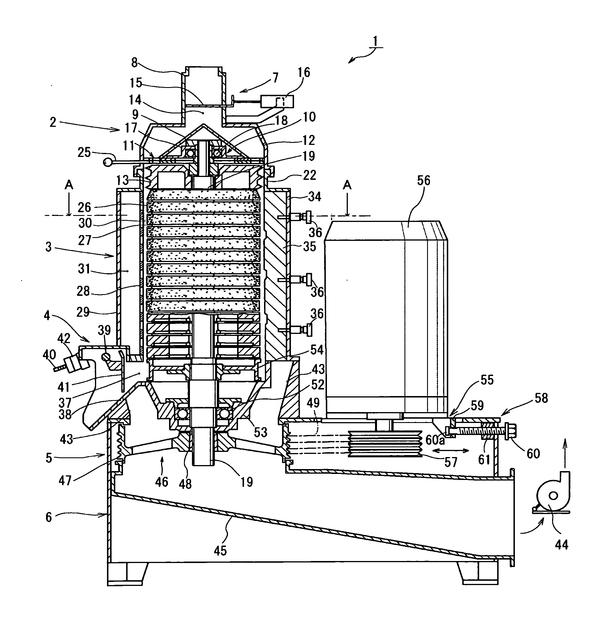
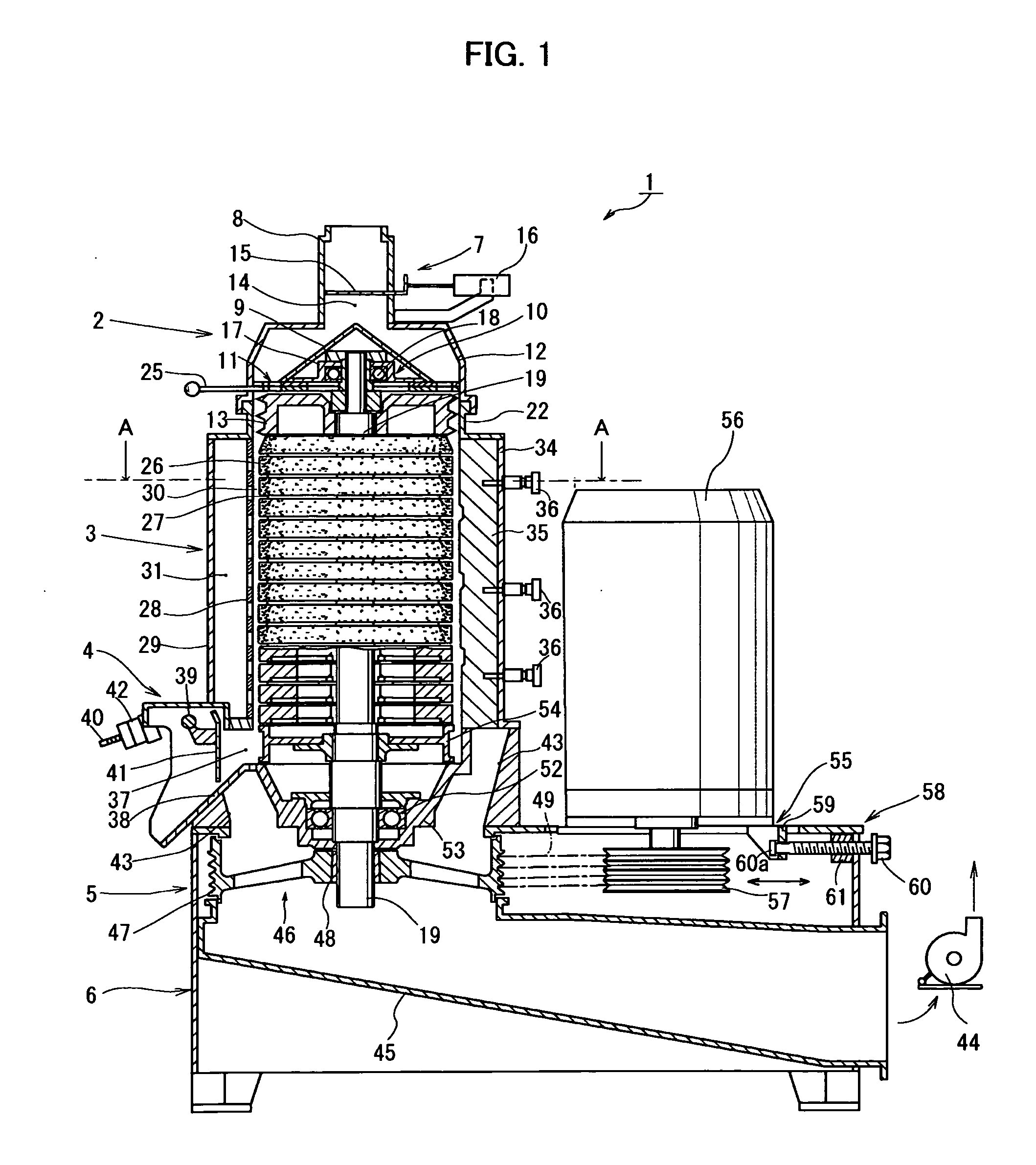
[0037]As shown in FIG. 1, a grinding type vertical grain milling machine 1 according to an embodiment of the invention mainly includes a grain supply unit 2 that supplies a grain to be milled, a grinding type grain milling unit 3 that mills the grain received from the grain supply unit 2 while conveying it to a lower grain discharge unit 4, the grain discharge unit 4 that discharges the grain milled at the grinding type grain milling unit 3, a bran collecting unit 5 that collects bran separated from a milled grain at the grinding type grain milling unit 3, and a body base portion 6 that supports a machine body and a motor as a driving source.

(Grain Supply Unit)

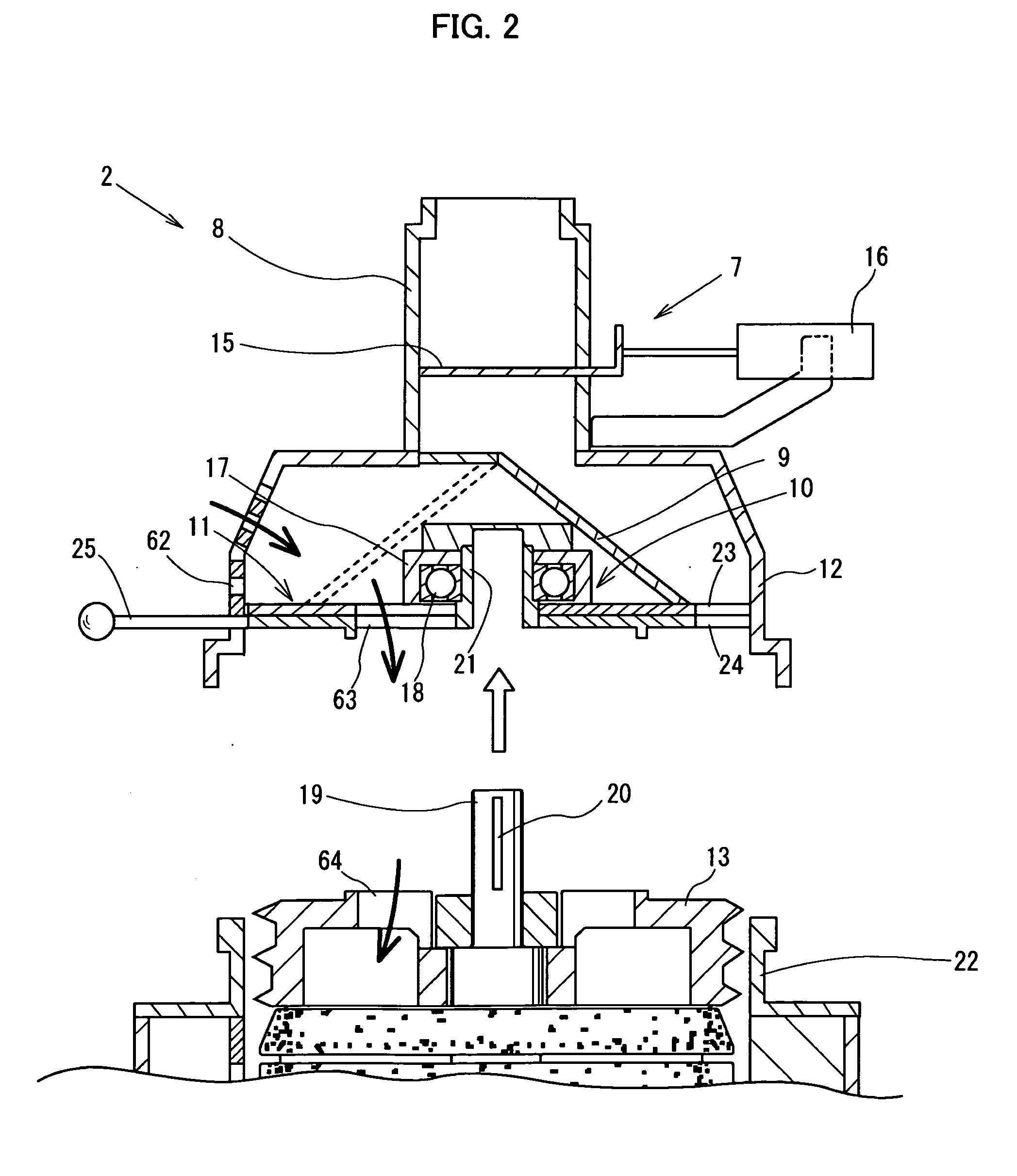
[0038]The grain supply unit 2 includes a grain supply cylinder 8 that receives a grain supplied from a raw material tank (not shown) or the like, a shutter mechanism 7 that is provided at the grain supply cylinder 8 so as to selective...


PUM

PropertyMeasurementUnit
Diameteraaaaaaaaaa
Diameteraaaaaaaaaa
Angular velocityaaaaaaaaaa

Abstract

A grinding type vertical grain milling machine is capable of shortening a dimension of a machine body in the vertical direction and removing bran by evenly suctioning an entire bran removing chamber. The grinding type vertical grain milling machine includes a bran removing metallic mesh cylinder with a main shaft, an integral grinding type grain milling roll body, a bran removing chamber, and a bran discharge pipe that discharges bran to the outside of the machine. A fan-pulley is provided between the bran removing chamber and the bran discharge pipe. The fan-pulley rotationally drives the main shaft to which the grinding type grain milling roll is axially attached and generates a bran removing wind to convey bran produced by the grain milling action of the grinding type grain milling roll from the bran removing chamber toward the bran discharge pipe.

Description

BACKGROUND OF THE INVENTION[0001]1. Field of the Invention[0002]The present invention relates to a grinding type vertical grain milling machine in which a cylindrical grinding type grain milling roll body is attached to a main shaft perpendicularly supported to a body base.[0003]2. Description of the Related Art[0004]An existing grinding type vertical grain milling machine is disclosed in Japanese Patent Nos. 3201496 and 4481269. The milling machine will be described with reference to the drawings. FIG. 6 is a longitudinal sectional view of the milling machine disclosed in Japanese Patent No. 3201496. A hollow main shaft 103 of which the lower end is opened is uprightly formed (perpendicularly supported) at the substantial center of the body base 102 by an upper bearing portion 105 and a lower bearing portion 104. Then, a plurality of annular grinding type grain milling rolls 107 are placed to overlap each other directly above the upper bearing portion 105, whereby a cylindrical int...

Claims


Application Information

Patent Timeline
IPC IPC(8): B02C7/13
CPCB02B3/04B02C7/08B02C7/13B02B7/00
Inventor SETO, YASUYOSHIKAJIHARA, KAZUNOBUNONAKA, KAZUTOKOIKE, YASUNORIYAMAMOTO, KOJI
Owner SATAKE CORP
Why Eureka
Try Eureka