
Tape reel and information recording medium

a technology of information recording medium and tape reel, which is applied in the field of tape reel and information recording medium, can solve the problems of difficult winding of magnetic tapes and deformation of flanges, and achieve the effect of increasing the strength of the inner wall

Inactive Publication Date: 2012-03-22
TDK CORPARATION
View PDF17 Cites 0 Cited by
  • Summary
  • Abstract
  • Description
  • Claims
  • Application Information

AI Technical Summary

Benefits of technology

[0005]The present invention was conceived in view of the problem described above and it is a main object of the present invention to provide a tape reel and an information recording medium capable of reliably preventing deformation of the flanges due to tightening of a magnetic tape when the magnetic tape is wound on.
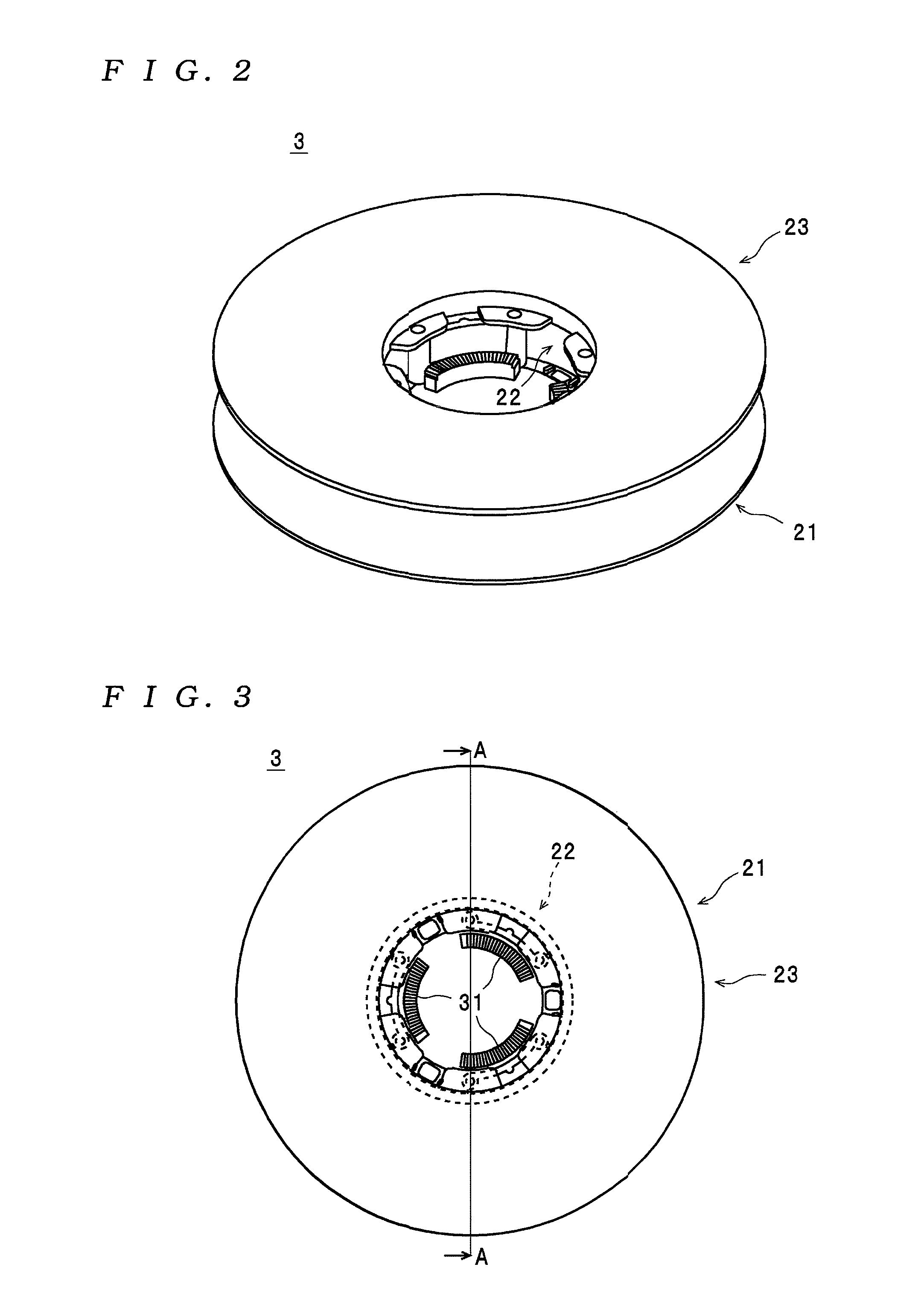
[0008]According to the tape reel and the information recording medium, the cylindrical body is constructed so as to include the bosses, in which the through-holes through which the joining pins erected on the first flange are inserted are formed, and the inner wall, the second flange is constructed so as to include the protruding portions including the through-holes through which the joining pins are inserted, and a plurality of the positioning pins that contact the surface on the outer circumferential wall side of the inner wall to position the cylindrical body are formed on the first flange. By doing so, even if the outer circumferential wall has deformed so as to become squeezed due to pressure applied by tightening of a magnetic tape when the magnetic tape is wound on, it is possible to maintain a state where pressure is not applied to the joining pins and the positioning pins. Therefore, according to the tape reel and the information recording medium, since it is possible to reliably prevent deformation of the first flange and the second flange due to pressure being applied to the joining pins and / or the positioning pins, it is possible to reliably prevent contact between the sides of a magnetic tape and the first flange and second flange when the magnetic tape is wound on.
[0010]By using such construction, even if the second flange is pressed onto the cylindrical body when the first flange, the cylindrical body, and the second flange are joined, a pressing force in the direction from the first flange toward the second flange does not act from the outer circumferential wall of the cylindrical body onto the second flange. This means it is possible to sufficiently suppress deformation where the outer circumferential edge of the second flange becomes outwardly opened away from the outer circumferential edge of the first flange. As a result, according to the tape reel and the information recording medium, it is possible to reliably avoid a situation where, due to the outer circumferential edge of the second flange being outwardly opened, a magnetic tape becomes wound on the tape reel in a state where the ends in the width direction of the magnetic tape are not aligned (a state where the tape reel is not properly wound on with the end portions of the magnetic tape in alignment), which can cause creasing of the tape, improper rotation of the tape reel, recording / reproduction errors, and the like.
[0012]By using such construction, even if the cylindrical body is pressed onto the first flange when the first flange, the cylindrical body, and the second flange are joined, the pressure will act upon the thickened portion that has high rigidity, making it possible to sufficiently suppress deformation where the outer circumferential edge of the first flange becomes outwardly opened away from the outer circumferential edge of the second flange. As a result, according to the tape reel and the information recording medium, it is possible to reliably prevent a situation where creasing of the tape, improper rotation of the tape reel, recording / reproduction errors, and the like occur due to the outer circumferential edge of the first flange becoming outwardly opened.
[0014]By using such construction, it is possible to more reliably position the cylindrical body with respect to the first flange and the second flange.
[0016]By using such construction, it is possible to sufficiently increase the strength of the inner wall.

Problems solved by technology

This means that when the hub ring deforms so as to become squeezed due to the magnetic tape being tightened, there is the risk of the parts where the notches are formed applying pressure to the bosses and such pressing forces causing the flanges to deform.
Accordingly, with the conventional tape reel, as before there is still the problem of the sides of the tape contacting the flanges when the magnetic tape is wound on and / or the gap between the two flanges narrowing and making it difficult to wind on a magnetic tape.

Method used


Image

  • Tape reel and information recording medium
  • Tape reel and information recording medium
  • Tape reel and information recording medium

Examples


Embodiment Construction

[0032]Preferred embodiments of a tape reel and an information recording medium according to the present invention will now be described with reference to the attached drawings.

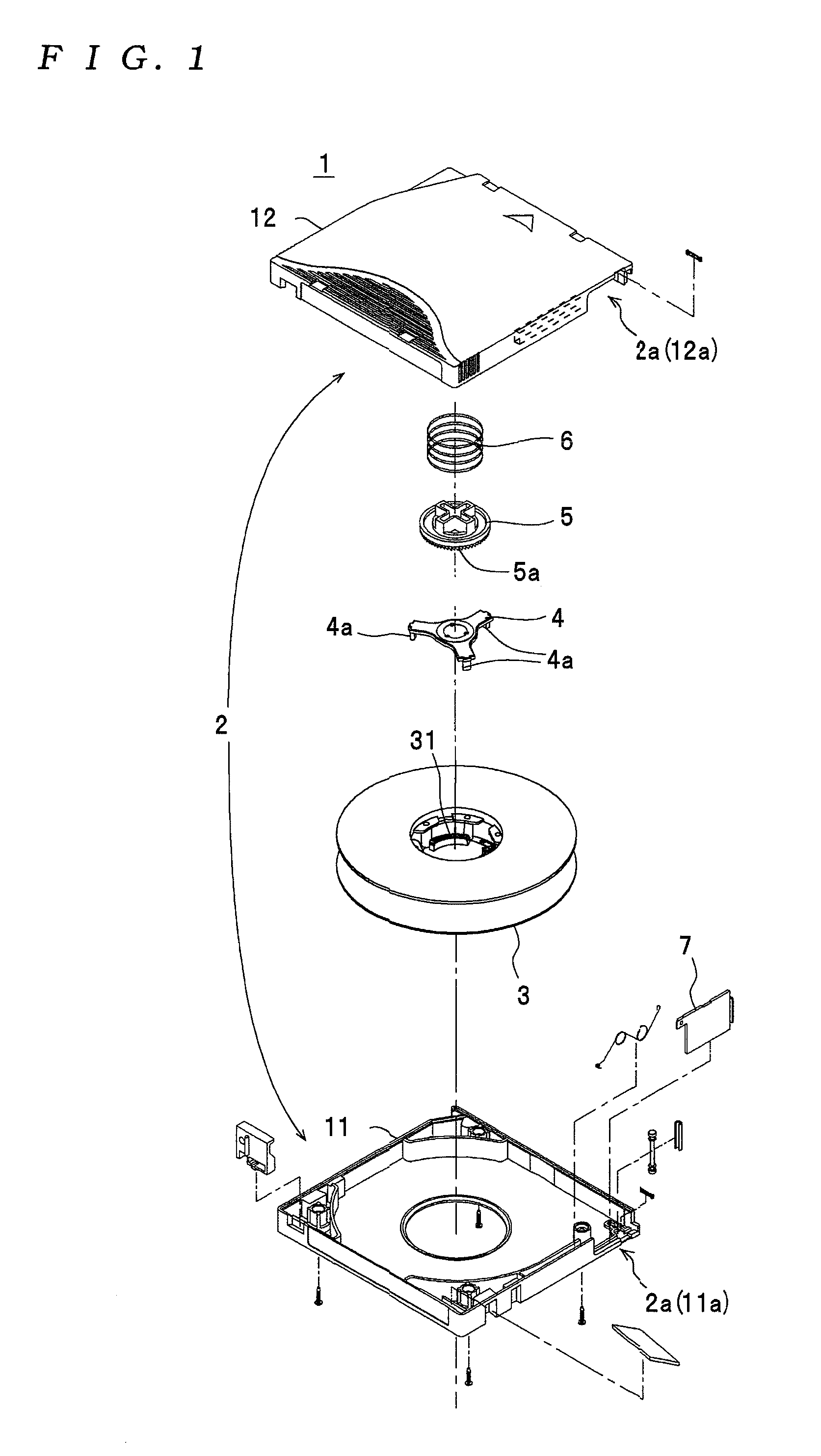
[0033]First, the construction of an information recording medium 1 will be described with reference to the drawings.

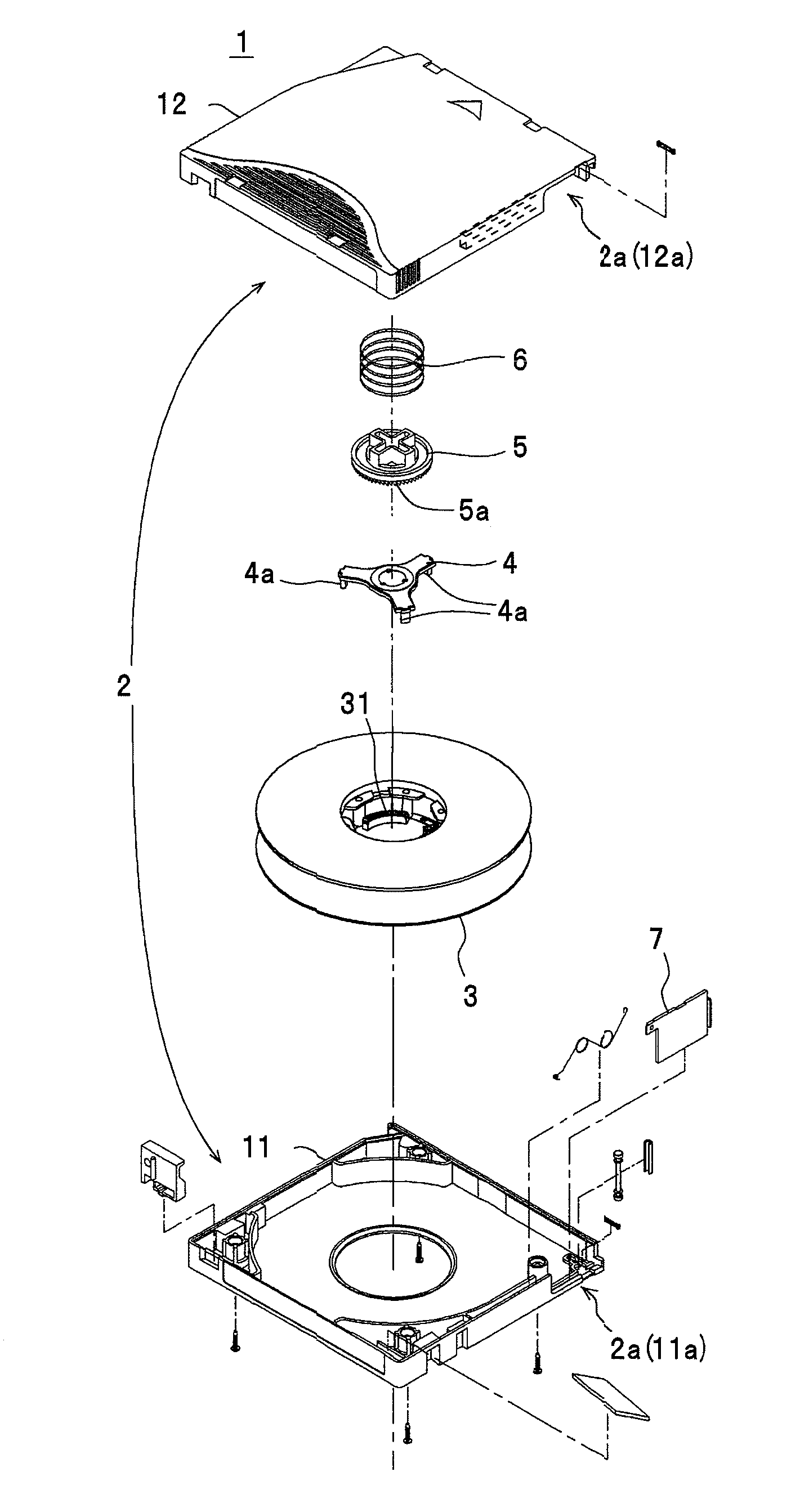
[0034]The information recording medium 1 shown in FIG. 1 is a single-reel type information recording medium used in a storage device for backing up recording data that has been recorded in an electronic computer for example, and as shown in the diagram, includes a case main body 2, a tape reel 3, a brake releasing plate 4, a locking member 5, a brake spring 6, and a door member 7. Note that although in reality a magnetic tape is wound around the tape reel 3 of the information recording medium 1, for ease of understanding the construction of the respective parts, the magnetic tape has been omitted from FIG. 1.

[0035]As shown in FIG. 1, the case main body 2 includes a lower case 11 and an upper case...


PUM

PropertyMeasurementUnit
outer diameteraaaaaaaaaa
diameter D1aaaaaaaaaa

Abstract

A tape reel includes a first flange, a cylindrical body, and a second flange formed separately. The first flange, the cylindrical body, and second flanges are joined with inner surfaces of the first and second flanges contacting the cylindrical body. Joining pins are erected on the inner surface of the first flange. The cylindrical body includes an outer wall, bosses with through-holes for the joining pins fixed to the inside of the outer wall, and an inner wall positioned inside and following the outer wall. The second flange has an opening formed in the center and a protrusion at an opening edge protruding toward the center and including through-holes through which the joining pins are inserted. Plural positioning pins that contact an outer surface of the inner wall in a state where the cylindrical body is contacted to position the cylindrical body are formed on the first and / or second flange.

Description

1. FIELD OF THE INVENTION[0001]The present invention relates to a tape reel around which a magnetic tape for recording information is wound and to an information recording medium equipped with such tape reel.2. DESCRIPTION OF THE RELATED ART[0002]As one example of this type of tape reel, a tape reel assembly (hereinafter simply “tape reel”) disclosed in Japanese Laid-Open Patent Publication No. 2001-118358 is known. This tape reel is used in a single reel-type information recording medium and includes an upper flange, a lower flange, and a hub ring. The upper flange, the lower flange, and the hub ring are formed separately (manufactured separately), with such parts being joined and assembled in a state where the hub ring has been positioned between the upper flange and the lower flange to construct a tape reel. Also, with such tape reel, by having bosses formed on both flanges engage notches formed in inner circumferential edges at both ends of the hub ring, rotation of the hub ring...

Claims


Application Information

Patent Timeline
Patent Type & Authority Applications(United States)
IPC IPC(8): B65H75/14G11B5/78B65H75/18
CPCB65H75/14G11B23/044B65H2701/5136B65H2701/378
Inventor SATOH, TAKATERUKOUZU, CHOTAROSUZUKI, HIROKITESHIMA, KEIJISHINKAWA, SHINTARO
Owner TDK CORPARATION
Learn More