Medical telemetry system and medical telemeter

Active Publication Date: 2012-03-22
NIHON KOHDEN CORP
View PDF6 Cites 19 Cited by
  • Summary
  • Abstract
  • Description
  • Claims
  • Application Information

AI Technical Summary

Benefits of technology

[0006]It is therefore an object of the invention to provide a medical telemetry system in which information for establishing communication to enable a biological signal transmitted from a telemeter to be receiv

Problems solved by technology

In the case where the manual input is not correctly carried out, such as that, while the telemeters are attached respectively to patients A and B as described above, the channel numbers are erroneously input so that channel 1 is corresponded to patient B and channel 2 is corresponded to patient A, biological signal data of patient A which is remotely monitored through channel 1

Method used


Image

  • Medical telemetry system and medical telemeter
  • Medical telemetry system and medical telemeter
  • Medical telemetry system and medical telemeter

Examples


first embodiment

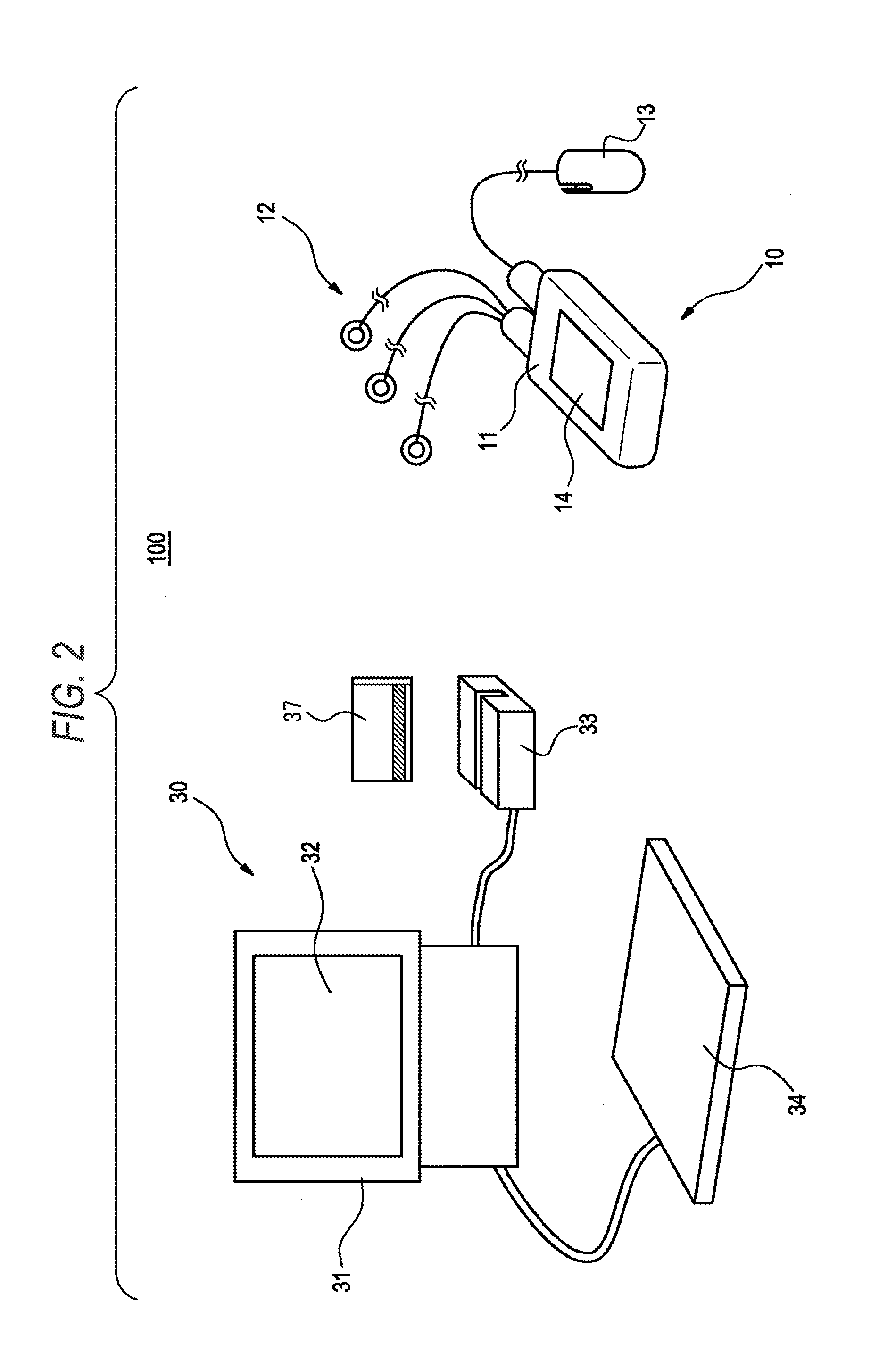
[0060]Next, a medical telemetry system 100 of the invention will be described with reference to FIG. 2.

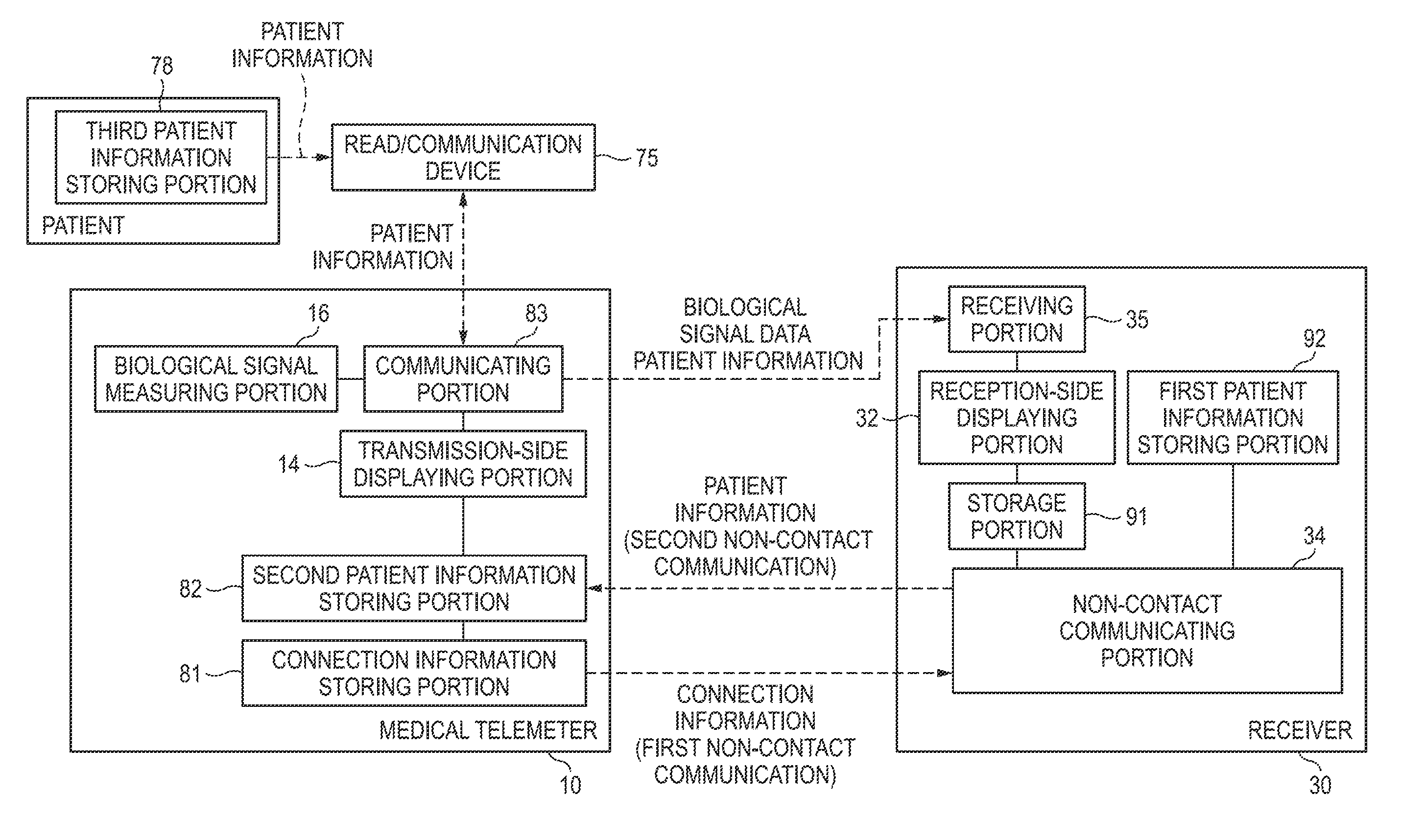
[0061]The telemeter 10 includes the telemeter body unit 11, an electrode group 12, a sensor probe 13, and a transmission-side displaying portion 14. The telemeter body unit 11 is configured so as to have the size and weight which allow a patient to carry it or move together therewith.

[0062]The electrode group 12 is to be attached to the chest region or limbs of a patient to detect an electrocardiogram, aspiration, and the like of the patient, and electrically connected to the telemeter body unit 11 through an electrode lead wire group.

[0063]The sensor probe 13 is attached to a finger of a patient to detect the pulse wave and blood oxygen saturation (SpO2) of the patient, and electrically connected to the telemeter body unit 11 through a sensor lead wire. The telemeter body unit 11 is configured so as to be connectable to a cuff which is not shown, and therefore it is possible to me...

second embodiment

[0126]According to the medical telemetry system 300A of the embodiment, in addition to the operations and functions which have been described in the second embodiment, the correspondence relationship between a patient and the medical telemeter 10B can be rechecked when the medical telemeter 10B is to be attached to the patient.

[0127]When the medical telemeter 10B is to be attached to a patient, a medical person such as a nurse reads the patient information carried by the patient ID 98, by using the read / communication device 75. In this state, at least one of transmission from the read / communication device 75 to the medical telemeter 10B, and that from the medical telemeter 10B to the read / communication device 75 is executed. As described above, at least one of the read / communication device 75 and the medical telemeter 10B determines coincidence of the patient information. If the patient information is not coincident, i.e., if the medical telemeter 10B is not attached to the patient ...


PUM


Abstract

A medical telemetry system includes: a medical telemeter including: a measuring portion which measures a biological signal of a patient as biological signal data; a communicating portion which wirelessly transmits the biological signal data; and a connection information storing portion which stores connection information; and a receiver including: a non-contact communicating portion which executes first non-contact communication to read the connection information in a non-contact manner; a storage portion which stores the connection information read by the non-contact communicating portion; and a receiving portion which starts reception of the biological signal data transmitted by the communicating portion, when the connection information is stored in the storage portion.

Description

BACKGROUND OF THE INVENTION[0001]The present invention relates to a medical telemetry system including a telemeter (transmission apparatus) which wirelessly transmits biological signal data that are acquired by measuring the blood pressure, heart rate, and the like of a living body, and a receiver which remotely receives the biological signal data.[0002]In an inpatient ward of a hospital or the like, such a medical telemetry system has been used for monitoring the condition of a patient. JP-A-2005-168600 discloses a related-art telemeter which is portable by a patient. A patient can freely move in an inpatient ward while measurements of biological signals are continued. A specific carrier frequency (wireless communication channel) which is used for wirelessly transmitting biological signal data to a receiver is allocated to the telemeter.[0003]An example of such a receiver is a central monitor which is disposed in a nurse's station or the like. A receiver of this kind can receive bi...

Claims


Application Information

Patent Timeline
IPC IPC(8): G08C15/06G16H40/67
CPCA61B5/0006A61B5/002G06F19/3418A61B2562/08A61B5/14551G16H40/67
Inventor MATSUMURA, FUMIYUKIHATAKEYAMA, HIROKAZUTANIGUCHI, HIROYUKITEZUKA, SHINJI
Owner NIHON KOHDEN CORP
Why Eureka
Try Eureka